|
Архитектура Аудит Военная наука Иностранные языки Медицина Металлургия Метрология Образование Политология Производство Психология Стандартизация Технологии |
|
|
Архитектура Аудит Военная наука Иностранные языки Медицина Металлургия Метрология Образование Политология Производство Психология Стандартизация Технологии |
DISTANCE MEASURING EQUIPMENT - INTRODUCTIONСтр 1 из 5Следующая ⇒
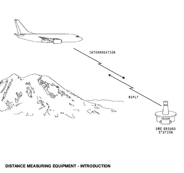
DISTANCE MEASURING EQUIPMENT - INTRODUCTION Purpose The distance measuring equipment (DME) system supplies slant range (line of sight) distance measurement between the airplane and the ground station. Abbreviations and Acronyms · AC - alternating current · ACP - audio control panel · ADF - automatic direction finder · alt - alternate · altn - alternate · app - approach · ARINC - Aeronautical Radio, Inc. · ATC - air traffic control · ATE - automatic test equipment · auto - automatic · B - both · BITE - built-in test equipment · BL - buttock line · CAPT - captain · CDU - control display unit · circ - circulator · CPU - central (control) processing unit · DC - direct current · DEU - display electronics unit · DME - distance measurement equipment · EFIS - electronic flight instrument system · F/O - first officer · FCC - flight control computer · FDAU - flight data acquisition unit · FMC - flight management computer · FMCS - flight management computer system · freq - frequency · fwd - forward · grd - ground · I/C - intercom · ILS - instrument landing system · LCD - liquid crystal display · LED - light emitting diode · LRU - line replacable unit · maint - maintenance · MHz - megahertz · MKR - marker beacon · nav - navigation · NCD - no computed data · ND - navigation display · NORM - normal · PFD - primary flight display · R - range · rcvr - receiver · REU - remote electronics unit · RF - radio frequency · rly - relay · R/T - receive/transmit · spkr - speaker · sta - station · TCAS - traffic alert and collision avoidance system · TFR - transfer · TX - transmitter · V - voice · V - volts · VHF - very high frequency · xfr - transfer · xmtr - transmitter · xpndr - transponder
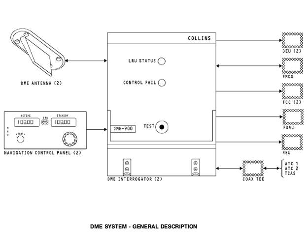
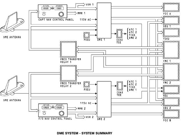
DME SYSTEM - GENERAL DESCRIPTION General The DME system has two DME interrogators and two antennas. Description The interrogators get manual tune inputs and flight management computer system (FMCS) autotune inputs from the navigation control panel. If the NAV control panel tune inputs fail, the interrogators get autotune inputs directly from the FMC. The DME system sends data to the display electronics units to show on the primary flight displays (PFDs) and navigation displays (NDs). The DME system sends data to these units: · Flight control computers (FCC) · Flight management computer System (FMCS) · Flight data acquisition unit (FDAU) · Remote Electronics Unit (REU). The FCCs use DME data as an input to calculate the VOR capture point in the autopilot VOR mode. The DME data is also used in the VOR mode to find when over station is sensed (OSS) for the VOR ground station. The FMCS uses DME data to calculate FMC position updates. The flight data acquisition unit receives DME data, formats it, and sends it to the flight data recorder. The REU receives audio from the DME station and sends it to the flight deck headsets and speakers. The DME system sends and receives a suppression pulse between these units: · DME · ATCs · TCAS. The DME interrogator receives the station audio identifiers and sends them to the remote electronics unit (REU).
General These are the components in the flight compartment that have an interface with the DME system: · FMC source select switch · Left inboard and outboard display units · Left and right EFIS control panels · Right inboard and outboard display units · Captain’s and first officer’s NAV control panel · Captain’s and first officer’s audio control panel.
DME SYSTEM - COMPONENT LOCATION - ELECTRONIC EQUIPMENT COMPARTMENT AND ANTENNAS DME Component Locations These components are in the electronics equipment compartment: · DME 1 interrogator · DME 2 interrogator. These components are on the exterior of the airplane: · DME 1 antenna · DME 2 antenna.
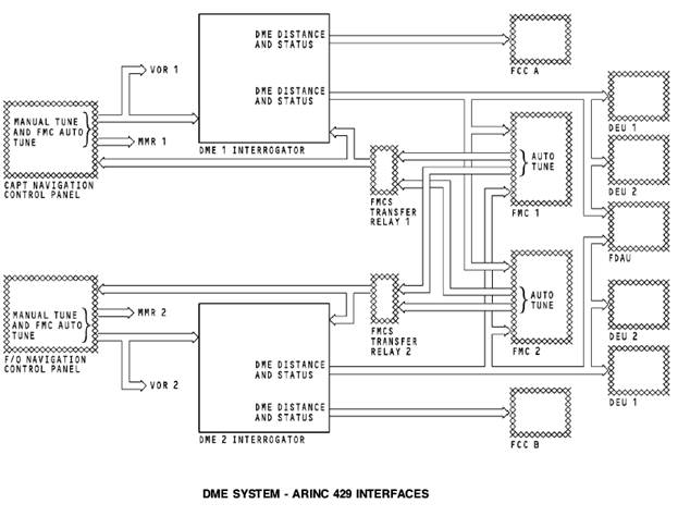
Navigation Control Panel The navigation control panels supply a manual tune frequency input to the DME interrogator. They also send four auto tune frequency inputs from the Flight Management Computer (FMC). The control panels send tune and test data on two output data buses. One output data bus goes to the MMR receiver and one output data bus goes to both the DME interrogator and VOR receiver. DME Outputs Each DME interrogator has two output buses. One output bus supplies data to the on-side flight control computer (FCC). DME 1 sends data to FCC A and DME 2 sends data to FCC B. the other Output bus supplies data to these units: · Flight management computer system (FMCS). · Display electronics units 1 and 2 · Flight data acquisition unit (FDAU). The FMCS uses DME distance to calculate position updates. The DEUs use DME distance for displays. The FDAU receives DME distance and formats it for the flight data recorder. Flight Management Computer The FMC supplies auto tune commands through the navigation control panel to the DME interrogator. If the navigation control panel has a failure, the DME gets auto tune signals directly from the FMC.
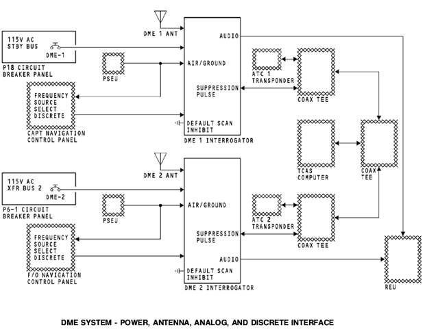
Power Interface Each DME interrogator receives 115v ac from the DME circuit breakers. DME Antenna Interface The DME antennas transmit and receive DME signals. The antennas transmit signals to the ground stations. They then receive the reply signals from the DME ground station and send them to the interrogator. Source Select Discrete The source select discrete controls the ARINC 429 receive ports in the DME interrogator. With the source select open, the DME interrogator gets manual and auto tune commands from the navigation control panel. If the navigation control panel has a failure, the source select discrete goes to ground. The DME then gets auto tune signals directly from the FMC. PSEU The proximity switch electronics unit (PSEU), supplies an air/ ground discrete inputs to the DME interrogators to set flight leg count. The air/ground discrete also goes to the navigation control panels to inhibit test commands in the air. DME/ATC/TCAS Suppression These systems operate in the same frequency band: · DME · Air traffic control (ATC) · Traffic alert and collision avoidance system (TCAS). When a DME interrogator, an ATC transponder, or the TCAS computer transmits, it sends a suppression pulse through the suppression lines. This pulse stops the reception of the other four units. This prevents damage to the receiver circuits of the other LRUs. DME Audio The DME interrogator sends the DME station audio identifier to the remote electronics unit (REU). The audio goes to the headsets and the flight interphone speakers.
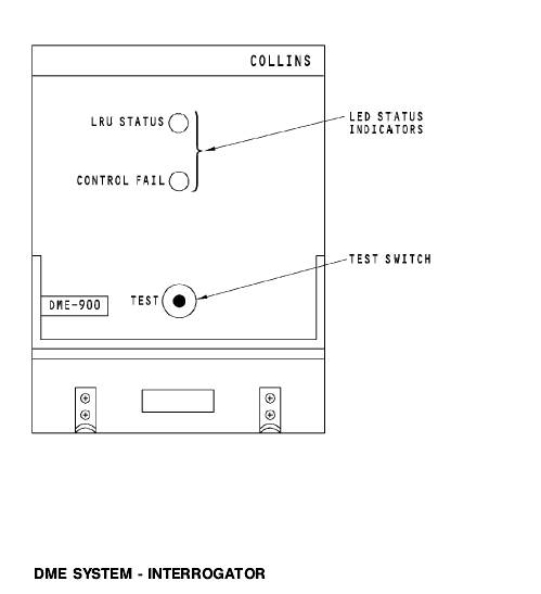
DME SYSTEM - INTERROGATOR General The DME interrogator tunes to 252 channels and calculates distance information for all the channels in the DME range. There are 200 DME channels for the VHF NAV frequencies. The other 52 channels are for military TACAN functions. The DME receive frequency is 63 MHz above or below the transmit frequency. Purpose These are the purposes of the DME interrogator: · Interrogate DME stations · Receive the station replies · Receive audio identifiers · Calculate slant range distances.
Frequencies These DME tuning frequencies are in the VHF band: · 108.00 to 117.95 MHz for DME stations with VOR or ILS · 133.30 to 135.95 MHz for DME only stations.
Front Panel The front panel of the DME interrogator has these features: · LED status indicators · A self test switch.
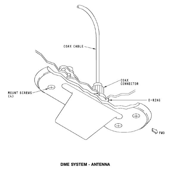
DME SYSTEM – ANTENNA General The L-band DME antenna transmits the interrogator output signal and receives the ground station reply and identification signals. Physical Description The antenna has an o-ring moisture seal and attaches to the airplane with four screws. The DME and the ATC antennas are the same and are interchangeable. Training Information Point Extra force on the antenna may be necessary to break the weatherproofing seal. To prevent damage to aircraft skin or electrical cable at the antenna base, carefully pry around the antenna with a sealant removal tool.
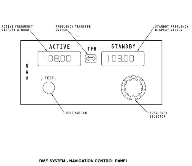
General The navigation (NAV) control panels supply frequency inputs and test commands to these navigation radios: · DME · ILS · VOR. When you put a paired VOR or ILS frequency into the navigation control panel, it also goes to the DME interrogator. The DME tunes a DME frequency in the range of 108MHz to 117.95MHZ. Set the frequency on the navigation control panel for these audio outputs: · VOR and DME station identification · ILS and DME station identification.
Operation The NAV control panels have an active frequency display window and a standby frequency display window. The frequency that shows in the active frequency display window is the frequency that the navigation radios use for operation. The standby frequency display window shows the next frequency you will use. The transfer switch is a momentary action switch. It transfers the frequency in the standby frequency display window to the active frequency display window. When you push the switch, the frequency that is in the active frequency display window transfers to the standby frequency display window. The frequency select control is a continuous rotary knob. There is an inner knob and an outer knob. The outer knob sets the tens and ones. The inner knob sets the tenth and one hundreth numbers. At power up, the frequency displays show the last frequency entry before power down. The NAV control panel continuous BITE function monitors the operation. The NAV control panel shows FAIL in the active and the standby frequency display windows when there is a failure. The monitor in the NAV control panel monitors the 28v dc input. If the monitor does not get the 28v dc, the frequency display windows are blank. Test When you push the test switch, the NAV control panel sends a test command out on it’s output bus. If a VOR frequency shows in the active frequency window, the test command goes to the VOR receiver. IF an ILS frequency shows in the active frequency window, the control panel sends a test command to the ILS receivers. If there is a DME frequency that is paired with the VOR or ILS frequency, a test command also goes to the DME interrogators. When you do a test of the master dim and test system, the NAV control panel shows 188.88. The display shows for two seconds on then one second off until the test is complete.
General The audio control panels (ACP) permit the crew to hear the DME station identification signals. The identification signals are 1350 Hz. The EFIS control Panel mode selector switch selects the NAV display modes that show DME distance. Audio Controls Set these controls on the audio control panel to listen to DME audio: · Push ON the NAV receiver volume control (NAV 1 for DME 1 and NAV 2 for DME 2) · Select B (both) or R (range) on the voice range filter switch · Set the NAV receiver volume control. The voice/range selector permits you to hear DME audio. You will hear the DME audio when the voice/range selector is in the R or B position. EFIS Controls The EFIS control panel mode selector switch must be in the VOR/ILS position to show DME distance on the top right of the ND. You put the VOR/ADF 1 switch to VOR 1 to show DME 1 in the lower left corner of the ND. DME 2 shows in the lower right corner of the ND when the VOR/ADF 2 switch is put to VOR 2.
DME SYSTEM - DISPLAY Normal PFD Display The left PFD shows DME 1 data. The right PFD shows the DME 2 data. The DME distance display shows in white letters and numbers. Normal RDMI Display The radio distance magnetic indication (RDMI) on the captain’s primary electronic flight instrument (EFIS) display shows DME distance. The first officer’s RDMI on the secondary EFIS shows the DME distance. The RDMI show DME 1 distance above the DME1 legend on the left side and DME 2 distance on the right side above the DME2 legend. The DME distance display shows in white letters and numbers. Normal ND Display DME distance shows on the top right corner of these ND displays: · Expanded and centered VOR · Expanded and centered ILS. The DME also shows in the lower left (VOR 1) and the lower right (VOR 2) corner of the ND if you select VOR on the EFIS control panel. DME NCD or Failed Displays Amber dashes replace numbers when the DME distance is no computed data (NCD). If the DME has a failure, an amber DME flag replaces the DME distance. The NCD and fail flag show in amber. DME NCD and Fail Displays White dashes replace the DME distance when the DME distance data is no computed data (NCD). If the DME has a failure, the DME amber flag replaces the DME distance.
Normal Tune Input The navigation control panel is the normal source for tune inputs. The flight management computer (FMC) sends up to four channels of auto tune signals to the navigation control panel. The navigation control panel adds one manual channel and sends five tune channels to the DME interrogator. Alternate Tune Input If the navigation control panel has a failure, the FMC sends auto signals directly to the DME interrogator. Discrete Inputs When the navigation control panel has a failure, it grounds a source select discrete to the DME central processing unit (CPU). The CPU changes the input from the navigation control panel to the FMC. The proximity switch electronics unit (PSEU)supplies an air/ ground discrete to prevent a DME test when the aircraft is in the air. The discrete also supplies flight leg data. Operation The CPU uses tune inputs to tune the frequency synthesizer. The CPU give a signal to the transmitter to send interrogation pulses. The transmit pulses go through a circulator then to the DME antenna. The transmitter sends a signal to the suppression circuits. During a transmission, the suppression circuit in the DME 1 interrogator sends a suppression pulse to these units: · DME 2 interrogator · ATC 1 and 2 transponders (XPNDR) · TCAS computer. The suppression pulse stops receiver operation in the other LRUs to prevent damage to internal circuits.
Receive The circulator sends the RF pulse pairs it receives from the antenna to the receiver. The receiver sends the pulse pair to the CPU. The CPU calculates the slant range distance. It uses the time it takes to transmit pulse pairs and get a reply from the ground station. When another L-band system transmits, a suppression pulse stops the receiver operation. Interrogator Output After the CPU calculates slant range distance, the CPU sends it to two ARINC 429 transmitters. One ARINC 429 transmitter sends the range data to the DEUs for the flight deck displays and to other systems. A second ARINC 429 transmitter sends range data to the flight control computer. The CPU sends the pulse pairs to the pulse pair decoder. The decoder sends the DME audio to the REU.
Bite Module The built-in test equipment (BITE) in the CPU monitors the circuits in the DME interrogator for faults. The fault memory in the DME keeps the number of faults per flight. Shop personnel can read the fault memory contents. Test The CPU does a test of the interrogator when it receives a test command from the navigation control panel. You can also push the test switch on the front panel of the interrogator. The LEDs on the front panel of the interrogator do not show during the navigation control panel test.
DME SYSTEM - SELF TEST Self Test Push the test switch on the DME interrogator to start a DME selftest. Front Panel Displays The LED status indicators go through this sequence: · The LRU status and control fail LEDs come on red for two seconds. · The LRU status LED changes to green. · All LEDs go off for two seconds. · The applicable LEDs come on to show the LRU status. The red CONTROL FAIL LED shows when the tuning source is invalid. The LRU STATUS LED shows interrogator test results. The LRU STATUS LED shows green for a good test or it shows red for a test failure.
DME SYSTEM - TEST DISPLAY General During a ground test or a self test, the display units show these indications: · The DME fail condition for two seconds · The DME NCD condition for the next two seconds · The DME normal condition to end the test. The DME normal condition is the distance that shows before the test starts. DME indications also show in the lower left (VOR 1) and lower right (VOR 2) corner of the ND when you select VOR on the VOR/ADF switches on the EFIS control panels.
DISTANCE MEASURING EQUIPMENT - INTRODUCTION Purpose The distance measuring equipment (DME) system supplies slant range (line of sight) distance measurement between the airplane and the ground station. |
Последнее изменение этой страницы: 2019-06-19; Просмотров: 259; Нарушение авторского права страницы