
|
Архитектура Аудит Военная наука Иностранные языки Медицина Металлургия Метрология Образование Политология Производство Психология Стандартизация Технологии |
|
|
Архитектура Аудит Военная наука Иностранные языки Медицина Металлургия Метрология Образование Политология Производство Психология Стандартизация Технологии |
Electric generators and motors ⇐ ПредыдущаяСтр 5 из 5
Other important energy-conversion devices emerged during the 19th century. During the early 1830s the English physicist and chemist Michael Faraday discovered a means by which to convert mechanical energy into electricity on a large scale. While engaged in experimental work on magnetism, Faraday found that moving a permanent magnet into and out of a coil of wire induced an electric current in the wire. This process, called electromagnetic induction, provided the working principle for electric generators. During the late 1860s Zé nobe-Thé ophile Gramme, a French engineer and inventor, built a continuous-current generator. Dubbed the Gramme dynamo, this device contributed much to the general acceptance of electric power. By the early 1870s Gramme had developed several other dynamos, one of which was reversible and could be used as an electric motor. Electric motors, which convert electrical energy to mechanical energy, run virtually every kind of machine that uses electricity. All of Gramme's machines were direct-current (DC) devices. It was not until 1888 that Nikola Tesla, a Serbian-American inventor, introduced the prototype of the present-day alternating-current (AC) motor. Direct energy-conversion devices Most of these energy converters, sometimes called static energy-conversion devices, use electrons as their “working fluid” in place of the vapour or gas employed by such dynamic heat engines as the external-combustion and internal-combustion engines mentioned above. In recent years, direct energy-conversion devices have received much attention because of the necessity to develop more efficient ways of transforming available forms of primary energy into electric power. Four such devices—the electric battery, the fuel cell, the thermoelectric generator (or at least its working principle), and the solar cell—had their origins in the early 1800s. The battery, invented by the Italian physicist Alessandro Volta about 1800, changes chemical energy directly into an electric current. A device of this type has two electrodes, each of which is made of a different chemical. As chemical reactions occur, electrons are released on the negative electrode and made to flow through an external circuit to thepositive electrode. The process continues until the circuit is interrupted or one of the reactants is exhausted. The forerunners of the modern dry cell and the lead-acid storage battery appeared during the second half of the 19th century. The fuel cell, another electrochemical producer of electricity, was developed by William Robert Grove, a British physicist, in 1839. In a fuel cell, continuous operation is achieved by feeding fuel (e.g., hydrogen) and an oxidizer (oxygen) to the cell and removing the reaction products. Thermoelectric generators are devices that convert heat directly into electricity. Electric current is generated when electrons are driven by thermal energy across a potential difference at the junction of two conductors made of dissimilar materials. This effect was discovered by Thomas Johann Seebeck, a German physicist, in 1821. Seebeck observed that a compass needle near a circuit made of different conducting materials was deflected when one of the junctions was heated. He investigated various materials that produce electric energy with an efficiency of3 percent. This efficiency was comparable to that of the steam engines of the day. Yet, the significance of the discovery of the thermoelectric effect went unrecognized as a means of producing electricity because of Seebeck's misinterpretation of the phenomenon as a magnetic effect caused by a difference in temperature. A basic theory of thermoelectricity was finally formulated during the early 1900s, though no functional generators were developed until much later. In a solar cell, radiant energy drives electrons across a potential difference at a semiconductor junction in which the concentrations of impurities are different on the two sides of the junction. What is often considered the first genuine solar cell was built in the late 1800s by Charles Fritts, who used junctions formed by coating selenium (a semiconductor) with an extremely thin layer of gold (see Exploiting renewable energy sources below). Text B Direct-Current (DC) Generators
If an armature revolves between two stationary field poles, the current in the armature moves in one direction during half of each revolution and in the other direction during the other half. To produce a steady flow of unidirectional, or direct, current from such a device, it is necessary to provide a means of reversing the current flow outside the generator once during each revolution. In older machines this reversal is accomplished by means of a commutator, a split metal ring mounted on the shaft of the armature. The two halves of the ring are insulated from each other and serve as the terminals of the armature coil. Fixed brushes of metal or carbon are held against the commutator as it revolves, connecting the coil electrically to external wires. As the armature turns, each brush is in contact alternately with the halves of the commutator, changing position at the moment when the current in the armature coil reverses its direction. Thus there is a flow of unidirectional current in the outside circuit to which the generator is connected. DC generators are usually operated at fairly low voltages to avoid the sparking between brushes and commutator that occurs at high voltage. The highest potential commonly developed by such generators is 1500 V. In some newer machines this reversal is accomplished using power electronic devices, for example, diode rectifiers. Modern DC generators use drum armatures that usually consist of a large number of windings set in longitudinal slits in the armature core and connected to appropriate segments of a multiple commutator. In an armature having only one loop of wire, the current produced will rise and fall depending on the part of the magnetic field through which the loop is movingA commutator of many segments used with a drum armature always connects the external circuit to one loop of wire moving through the high-intensity area of the field, and as a result the current delivered by the armature windings is virtually constant. Fields of modern generators are usually equipped with four or more electromagnetic poles to increase the size and strength of the magnetic field. Sometimes smaller interpoles are added to compensate for distortions in the magnetic flux of the field caused by the magnetic effect of the armature. DC generators are commonly classified according to the method used to provide field current for energizing the field magnets. A series-wound generator has its field in series with the armature, and a shunt-wound generator has the field connected in parallel with the armature. Compound-wound generators have part of their fields in series and part in parallel. Both shunt-wound and compound-wound generators have the advantage of delivering comparatively constant voltage under varying electrical loads. The series-wound generator is used principally to supply a constant current at variable voltage. A magneto is a small DC generator with a permanent-magnet field. Words and expressions armature - якорь commutator - коллектор, коммутатор. переключатель terminal - зажим, клемма, наконечник rectifiers - выпрямитель winding - обмотка loop - виток, контур distortion - искажение flux - поток compound-wound generator - генератор со смешанным возбуждением shunt-wound generator - генератор с параллельным возбуждением series-wound generator - последовательно соединенный генератор magneto - магнитоэлектрическая машина
Exercise 1 Ответьте на следующие вопросы: 1. How does current move during the revolution of an armature between two stationary field poles? 2. What is necessary to produce a steady flow of or direct current? 3. What is held against the commutator as it revolves? 4. What happens as the armature turns? 5. Is there a flow of unidirectional current in the outside circuit to which the generator is connected? 6. Why DC generators are usually operated at low voltages? 7. What is highest potential developed by DC generators? 8. What kind of armatures are used in modern DC generators? 9. Why are the fields of modern generators equipped with four or more electromagnetic poles? 10. What devices are added to compensate for distortions in the magnetic flux of the field caused by the magnetic effect of the armature? 11. How generators are commonly classified? 12. What are the advantages of compound-wound and shunt-wound generators? 13. What is the main application of series-wound generator? Exercise 2 Заполните пропуски недостающими по смыслу словами, используя текст: 1. If an … revolves between two stationary field poles, the current in the armature moves in one … during half of each revolution and in the … direction during the other half. 2. Fixed brushes of metal or carbon are held against the … as it revolves. 3. DC generators are usually operated at … voltages. 4. The highest potential commonly developed by … generators is 1500 V. 5. Modern DC generators use drum … that usually consist of a large number of windings. 6. In an armature having only one loop of wire, the current produced will … and … depending on the part of the magnetic field through which the loop is moving. 7. Fields of modern generators are usually equipped with … or more electromagnetic poles. 8. DC generators are classified according to the method used to provide … for energizing the field magnets. 9. A shunt-wound generator has the field connected in … with the armature. 10. Compound-wound generators have part of their … in series and part in parallel. 11. Compound-wound generators have the advantage of delivering comparatively constant … under varying electrical loads. Exercise 3 Соответствуют ли данные предложения содержанию текста: 1. AC generators are usually operated at fairly low voltages to avoid the sparking between brushes and commutator. 2. The highest potential commonly developed by DC generators is 1500 V. 3. Modern DC generators use drum armatures that usually consist of a large number of windings. 4. DC generators are rarely classified according to the method used to provide field current for energizing the field magnets. 5. A series-wound generator has its field in parallel with the armature. 6. A shunt-wound generator has the field connected in series with the armature. 7. Compound-wound generators have part of their fields in series and part in parallel. 8. Shunt-wound and compound-wound generators have the disadvantage of delivering variable voltage under constant electrical loads. 9. A magneto is a small AC generator with a permanent-magnet field. Exercise 4 Используя текст, составьте высказывания с данными словами и выражениями: Revolution of an armature – steady flow of current - to reverse the current – to be mounted on – to be insulated from each other - to serve as – to be held against – to be in contact alternately with – to reverse direction - to be operated at – to consist of – to be set in – to be delivered by – to be equipped with – to be added to compensate - to increase the size and strength – to be caused by - to be classified according to – to have the advantage of - to be used principally to. Exercise 5 Кратко передайте содержание каждого абзаца.
Exercise 6 Выделите пять основных идей текста.
Exercise 7 Составьте предложения, используя данные выражения: · armature (якорь); drum armature (барабанный якорь); disc-type armature (дисковый якорь); meter armature (якорь счетчика); ring armature (кольцевой якорь); shuttle armature (якорь Н-образного сечения); smooth-core (гладкий якорь, без пазов)); spider armature (якорная звезда). · commutator (переключатель); battery commutator (полюсной переключатель); electronic commutator (электронный переключатель); flat-spot commutator (коллектор с местной выработкой); plug commutator (штепсельный переключатель); shrink-ring commutator (коллектор с бандажами); split-ring commutator (коллектор из двух полуколец). · terminal ( зажим, клемма, вывод); battery terminal (полюс батареи); connecting terminal (зажим, клемма); earth terminal (заземляющий зажим); outlet terminal (трансформаторный ввод); pole terminal (полюсный наконечник); spade (наконечник для многожильного кабеля). · rectifier (выпрямитель); arc rectifier (дуговой выпрямитель); biphase rectifier (двухфазный выпрямитель); crystal rectifier (кристаллический выпрямитель ); dry rectifier (металлический выпрямитель); electrolytic rectifier (электролитический выпрямитель); electron rectifier (кенотронный выпрямитель); heavy-duty rectifier ( мощный кенотрон); mechanical rectifier (механический выпрямитель); mercury-arc rectifier (ртутный выпрямитель); pulsed rectifier (импульсный выпрямитель); valve rectifier (кенотронный выпрямитель, кенотрон). · winding (обмотка); armature winding (обмотка якоря); auxiliary winding (вспомогательная обмотка ); closed-coil winding (замкнутая обмотка); drum winding (барабанная обмотка); primary winding (первичная обмотка); starting winding (пусковая обмотка); exciting winding (обмотка возбуждения). · distortion (искажение); distortion of field (смещение поля); amplitude distortion (амплитудное искажение); frequency distortion (частотное искажение); phase distortion (фазовое искажение). Exercise 8 Переведите на русский язык следующие предложения:
1. Thermoelectric generators are devices that convert heat directly into electricity. 2. Electric current is generated when electrons are driven by thermal energy across a potential difference at the junction of two conductors made of dissimilar materials. 3. A direct-current (DC) generator is a rotating machine that supplies an electrical output with unidirectional voltage and current. 4. Voltage is induced in coils by the rate of change of the magnetic field through the coils as the machine rotates. 5. The field is produced by direct current in field coils or by permanent magnets on the stator. 6. In practical machines, the rotor contains many coils symmetrically arranged in slots around the periphery and all connected in series. 7. The voltage magnitude is proportional to the rotor speed and the magnetic flux. 8. Control of output voltage is normally provided by control of the direct current in the field. 9. For convenience in design, direct-current generators are usually constructed with four to eight field poles. 10. The number of stationary brushes bearing on the rotating commutator is usually equal to the number of poles but may be only two in some designs. 11. Direct-current generators were widely used prior to the availability of economical rectifier systems supplied by alternators. 12. In some applications, the direct-current generator retains an advantage over the alternator-rectifier in that it can operate as a motor as well, reversing the direction of power flow.
Exercise 9 Переведите на английский язык: 1. В генераторах постоянного тока якорь вращается между двумя постоянными полевыми полюсами. 2. Для обеспечения устойчивого потока однонаправленного тока от генератора постоянного тока, необходимо обеспечить изменение направления тока единожды в течение каждого вращения якоря. 3. В старых генераторах постоянного тока, движение в обратном направлении достигалось при помощи коммутатора. 4. Изолированные друг от друга полукольца служат терминалами катушки якоря. 5. Металлические щетки, установленные перед коммутатором соединяют катушку с внешними проводами. 6. Во время вращения якоря, каждая щетка поочередно контачит с половинами коммутатора. 7. Генераторы постоянного тока обычно используются для выработки низкого напряжения. 8. Напряжение, вырабатываемое генераторами постоянного тока, не превышает уровня 1500 вольт. 9. Величина и сила магнитного поля напрямую виляет на мощность генератора. Exercise 10 Текст на самостоятельный перевод: DC Motors In general, DC motors are similar to DC generators in construction. They may, in fact, be described as generators “run backwards.” When current is passed through the armature of a DC motor, a torque is generated by magnetic reaction, and the armature revolves. The action of the commutator and the connections of the field coils of motors are precisely the same as those used for generators. The revolution of the armature induces a voltage in the armature windings. This induced voltage is opposite in direction to the outside voltage applied to the armature, and hence is called back voltage or counter electromotive force (emf). As the motor rotates more rapidly, the back voltage rises until it is almost equal to the applied voltage. The current is then small, and the speed of the motor will remain constant as long as the motor is not under load and is performing no mechanical work except that required to turn the armature. Under load the armature turns more slowly, reducing the back voltage and permitting a larger current to flow in the armature. The motor is thus able to receive more electric power from the source supplying it and to do more mechanical work. Because the speed of rotation controls the flow of current in the armature, special devices must be used for starting DC motors. When the armature is at rest, it has virtually no resistance, and if the normal working voltage is applied, a large current will flow, which may damage the commutator or the armature windings. The usual means of preventing such damage is the use of a starting resistance in series with the armature to lower the current until the motor begins to develop an adequate back voltage. As the motor picks up speed, the resistance is gradually reduced, either manually or automatically. The speed at which a DC motor operates depends on the strength of the magnetic field acting on the armature, as well as on the armature current. The stronger the field, the slower is the rate of rotation needed to generate a back voltage large enough to counteract the applied voltage. For this reason the speed of DC motors can be controlled by varying the field current.
Text D Alternating-Current (AC) Generators (Alternators) A simple generator without a commutator will produce an electric current that alternates in direction as the armature revolves. Such alternating current is advantageous for electric power transmission, and hence most large electric generators are of the AC type. In its simplest form, an AC generator differs from a DC generator in only two particulars: the ends of its armature winding are brought out to solid unsegmented slip rings on the generator shaft instead of to commutators, and the field coils are energized by an external DC source rather than by the generator itself. Low-speed AC generators are built with as many as 100 poles, both to improve their efficiency and to attain more easily the frequency desired. Alternators driven by high-speed turbines, however, are often two-pole machines. The frequency of the current delivered by an AC generator is equal to half the product of the number of poles and the number of revolutions per second of the armature. It is often desirable to generate as high a voltage as possible, and rotating armatures are not practical in such applications because of the possibility of sparking between brushes and slip rings and the danger of mechanical failures that might cause short circuits. Alternators are therefore constructed with a stationary armature within which revolves a rotor composed of a number of field magnets. The principle of operation is exactly the same as that of the AC generator described, except that the magnetic field (rather than the conductors of the armature) is in motion. The current generated by the alternators described above rises to a peak, sinks to zero, drops to a negative peak, and rises again to zero a number of times each second, depending on the frequency for which the machine is designed. Such current is known as single-phase alternating current. If, however, the armature is composed of two windings, mounted at right angles to each other, and provided with separate external connections, two current waves will be produced, each of which will be at its maximum when the other is at zero. Such current is called two-phase alternating current. If three armature windings are set at 120° to each other, current will be produced in the form of a triple wave, known as three-phase alternating current. A larger number of phases may be obtained by increasing the number of windings in the armature, but in modern electrical-engineering practice three-phase alternating current is most commonly used, and the three-phase alternator is the dynamoelectric machine typically employed for the generation of electric power. Voltages as high as 13, 200 are common in alternators. Words and expressions
power transmission - передача энергии efficiency - коэффициент полезного действия, эффективность mechanical failure - механическое повреждение frequency - частота; повторяемость элементов connection - соединение; включение; соедини- тельная деталь generation - генерация
Exercise 1 Ответьте на следующие вопросы:
1. What type of current is advantageous for electric power transmission? 2. What is the type of the largest electric generators? 3. What is the general difference between AC and DC generators? 4. What is the easiest way to attain the desired frequency in AC generators? 5. How the frequency of the current delivered by an AC generator can be calculated? 6. Are rotating armatures practical in generation of high voltage? 7. What is the difference in principle of operation of alternators and AC generators? 8. How alternators generate a single-phase alternating current? 9. How larger number of phases may be obtained? Exercise 2 Заполните пропуски недостающими по смыслу словами, используя текст:
1. Alternating current is … for electric power transmission. 2. In AC generators the field coils are energized by an … DC source. 3. Low-speed AC generators have as many as 100 poles to … their efficiency. 4. The frequency of the … delivered by an AC generator is equal to half the product of the number of poles. 5. In generation of high voltage the rotating … are not practical. 6. Alternators are constructed with a … armature. 7. The principle of operation alternator is exactly the same as that of the AC generator except that the … field is in motion. 8. If the armature of generator is composed of two windings it generates … alternating current. 9. The current produced in the form of a triple wave is known as … alternating current. 10. A larger number of … may be obtained by increasing the number of windings in the armature. Exercise 3 Соответствуют ли данные предложения содержанию текста:
1. A simple generator without a commutator will produce an electric current that alternates in the opposite direction as the armature revolves. 2. Direct current is advantageous for electric power transmission. 3. There is no any difference between AC and DC generators. 4. Low-speed AC generators are built with as many as 100 poles. 5. The frequency of the current delivered by an AC generator is equal to the product of the number of poles. 6. Rotating armatures are practical in generation of as high a voltage as possible. 7. Alternators are therefore constructed with a rotating armature and a rotor composed of a number of field magnets. 8. The principle of operation of alternators is the same as that of the AC generator. 9. If the armature of generator is composed of two windings it is called a single-phase generator. 10. If three armature windings in generator are set at 45° to each other such generator produces three-phase alternating current. 11. Voltages as high as 220 V are common in alternators. Exercise 4 Используя текст, составьте высказывания с данными словами и выражениями:
Armature revolution - alternating current - electric power transmission - simplest form of generator - armature winding - field coil - external source - low-speed generator - high-speed turbine - number of revolutions per second - as high a voltage as possible - danger of mechanical failure - short circuit - stationary armature - principle of operation - negative peak - single-phase alternating current – to be composed – to be mounted – to be employed for. Exercise 5 Кратко передайте содержание каждого абзаца.
Exercise 6 Выделите пять основных идей текста.
Exercise 7 Составьте предложения, используя данные выражения: · Source (источник); continuous source (непрерывно действующий источник); extended source (распределенный источник); feed source (источник питания); light source (источник света); packaged source (компактный источник ); volume source (объемный источник). · efficiency (к.п.д., эффективность); efficiency of control (совершенство управления); average efficiency (средний к.п.д); electrical efficiency (электрический к.п.д); energy efficiency (энергетическая отдача); heat efficiency (тепловой к.п.д); fuel efficiency (к.п.д по топливу); power transmittance efficiency (коэффициент передачи по мощности); transmission efficiency (к.п.д передачи); watt-hour efficiency (ватт-часовая отдача). · Failure (повреждение); electronic failure (выход из строя радиоаппаратуры); engine failure (отказ двигателя); fatigue failure (усталостное повреждение); power failure (перерыв в подаче энергии); premature failure (преждевременное разрушение); structural failure (поломка конструкции); voltage failure (электрический пробой). · connection (соединение); bolted-on connection (болтовое соединение); bullet connection (штепсельное соединение); chain connection (каскадное включение); ground connection (заземление); multiple connection (параллельное соединение); permanent connection (неразъемное соединение); series connection (последовательное соединение); series-parallel connection (последовательно-параллельное соединение); star connection (соединение звездой); step connection (ступенчатое включение).
Exercise 8 Переведите на русский язык следующие предложения: 1. During the early 1830s the English physicist and chemist Michael Faraday discovered a means by which to convert mechanical energy into electricity on a large scale. 2. Electric motors, which convert electrical energy to mechanical energy, run virtually every kind of machine that uses electricity. 3. In 1888 Nikola Tesla, a Serbian-American inventor, introduced the prototype of the present-day alternating-current (AC) motor. 4. Direct energy-conversion devices have received much attention because of the necessity to develop more efficient ways of transforming available forms of primary energy into electric power. 5. The battery, invented by the Italian physicist Alessandro Volta about 1800, changes chemical energy directly into an electric current. 6. Thermoelectric generators are devices that convert heat directly into electricity. 7. The inventor investigated various materials that produce electric energy with an efficiency of 5 percent or higher. 8. A basic theory of thermoelectricity was finally formulated during the early 1900s. Exercise 9 Переведите на английский язык:
1. Принцип работы простого генератора переменного тока заключается в том, что ток, вырабатываемый им, чередуется в направлении по мере вращения якоря. 2. Генераторы переменного тока используются для передачи электроэнергии на расстояние от источника энергии. 3. Генераторы переменного тока могут иметь до сотни полюсов. 4. Двухполюсные генераторы переменного тока приводятся в движение при помощи мощных турбин. 5. Величина тока, вырабатываемого генераторами переменного тока, зависит от количества полюсов и частоты вращения якоря. 6. Причиной короткого замыкания в двигателе, явилось механическое повреждение проводов. 7. Якорь в генераторах переменного тока находится в стационарном положении. 8. Двухфазный ток вырабатывается генераторами, имеющими две обмотки в якоре. 9. Генераторы переменного тока могут вырабатывать напряжение до 13500 вольт.
Exercise 10 Текст на самостоятельный перевод: AC Motors Two basic types of motors are designed to operate on polyphase alternating current, synchronous motors and induction motors. The synchronous motor is essentially a three-phase alternator operated in reverse. The field magnets are mounted on the rotor and are excited by direct current, and the armature winding is divided into three parts and fed with three-phase alternating current. The variation of the three waves of current in the armature causes a varying magnetic reaction with the poles of the field magnets, and makes the field rotate at a constant speed that is determined by the frequency of the current in the AC power line. The constant speed of a synchronous motor is advantageous in certain devices; however, in applications where the mechanical load on the motor becomes very great, synchronous motors cannot be used, because if the motor slows down under load it will “fall out of step” with the frequency of the current and come to a stop. Synchronous motors can be made to operate from a single-phase power source by the inclusion of suitable circuit elements that cause a rotating magnetic field. The simplest of all electric motors is the squirrel-cage type of induction motor used with a three-phase supply. The armature of the squirrel-cage motor consists of three fixed coils similar to the armature of the synchronous motor. The rotating member consists of a core in which are imbedded a series of heavy conductors arranged in a circle around the shaft and parallel to it. With the core removed, the rotor conductors resemble in form the cylindrical cages once used to exercise pet squirrels. The three-phase current flowing in the stationary armature windings generates a rotating magnetic field, and this field induces a current in the conductors of the cage. The magnetic reaction between the rotating field and the current-carrying conductors of the rotor makes the rotor turn. If the rotor is revolving at exactly the same speed as the magnetic field, no currents will be induced in it, and hence the rotor should not turn at a synchronous speed. In operation the speeds of rotation of the rotor and the field differ by about 2 to 5 percent. This speed difference is known as slip. Motors with squirrel-cage rotors can be used on single-phase alternating current by means of various arrangements of inductance and capacitance that alter the characteristics of the single-phase voltage and make it resemble a two-phase voltage. Such motors are called split-phase motors or condenser motors (or capacitor motors), depending on the arrangement used. Single-phase squirrel-cage motors do not have a large starting torque, and for applications where such torque is required, repulsion-induction motors are used. Miscellaneous Machines For special applications several combined types of dynamoelectric machines are employed. It is frequently desirable to change from direct to alternating current or vice versa, or to change the voltage of a DC supply, or the frequency or phase of an AC supply. One means of accomplishing such changes is to use a motor operating from the available type of electric supply to drive a generator delivering the current and voltage wanted. Motor generators, consisting of an appropriate motor mechanically coupled to an appropriate generator, can accomplish most of the indicated conversions. A rotary converter is a machine for converting alternating to direct current, using separate windings on a common rotating armature. The AC supply voltage is applied to the armature through slip rings, and the DC voltage is led out of the machine through a separate commutator. A dynamotor, which is usually used to convert low-voltage direct current to high-voltage direct current, is a similar machine that has separate armature windings. Pairs of machines known as synchros, selsyns, or autosyns are used to transmit torque or mechanical movement from one place to another by electrical means. They consist of pairs of motors with stationary fields and armatures wound with three sets of coils similar to those of a three-phase alternator. In use, the armatures of selsyns are connected electrically in parallel to each other but not to any external source. The field coils are connected in parallel to an external AC source. When the armatures of both selsyns are in the same position relative to the magnetic fields of their respective machines, the currents induced in the armature coils will be equal and will cancel each other out. When one of the armatures is moved, however, an imbalance is created that will cause a current to be induced in the other armature. The magnetic reaction to this current will move the second armature until it is in the same relative position as the first. Selsyns are widely used for remote-control and remote-indicating instruments where it is inconvenient or impossible to make a mechanical connection. DC machines known as amplidynes or rotortrols, which have several field windings, may be used as power amplifiers. A small change in the power supplied to one field winding produces a much larger corresponding change in the power output of the machine. These electrodynamic amplifiers are frequently employed in servomechanism and other control systems. Unit 5 Text B Electric Power Systems
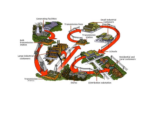
Electric Power Systems are the systems for the transformation of other types of energy into electrical energy and the transmission of this energy to the point of consumption. The production and transmission of energy in the form of electricity have important economic advantages in terms of cost per unit of power delivered. Electric power systems also make possible the utilization of hydroelectric power at a distance from the source. Alternating current (AC) is generally used in modern power systems, because it may be easily converted to higher or lower voltages by means of transformers. Thus, each stage of the system can be operated at an appropriate voltage. Such an electric power system consists of six main elements: the power station; a set of transformers to raise the generated power to the high voltages used on the transmission lines; the transmission lines; the substations at which the power is stepped down to the voltage on the subtransmission lines; the subtransmission lines; and the transformers that lower the subtransmission voltage to the level used by the consumer's equipment. In a typical system the generators at the central station deliver a voltage of from 1000 to 26, 000 volts (V); higher voltages are undesirable because of difficulties of This voltage is stepped up by means of transformers to values ranging from 138, 000 to 765, 000 V for the primary transmission line (the greater the voltage on the line, the less the current and consequently the less the power loss, the loss being proportional to the square of the current). At the substation the voltage may be transformed down to levels of 69, 000 to 138, 000 V for further transfer on the subtransmission system. The voltage is stepped down again by transformers to a distribution level such as 2400 or 4160 V or 15, 27, or 33 kilovolts (kV). Finally the voltage is transformed once again at the distribution transformer near the point of use to 240 or 120 V. The modern development of high-voltage solid-state rectifiers makes possible the economical conversion of high-voltage AC to high-voltage DC for power distribution, thus avoiding capacitive and inductive losses in transmission. The central station of a power system consists of a prime mover, such as a water or steam turbine, which operates an electric generator. Most of the world's electric power in the early 1990s was generated in steam plants driven by coal, oil, nuclear energy, or gas, with lesser percentages generated by hydroelectric, diesel, and internal-combustion plants. The lines of high-voltage transmission systems are usually composed of wires of copper, aluminum, or copper-clad or aluminum-clad steel, which are suspended from tall latticework towers of steel by strings of porcelain insulators. By the use of clad steel wires and high towers, the distance between towers can be increased, and the cost of the transmission line thus reduced. In modern installations with essentially straight paths, high-voltage lines may be built with as few as six towers to the mile. In some areas high-voltage lines are suspended from tall wooden poles spaced more closely together. For lower voltage subtransmission and distribution lines, wooden poles are generally used rather than steel towers. In cities and other areas where open lines create a hazard, insulated underground cables are used for distribution. Some of these cables have a hollow core through which oil circulates under low pressure. The oil provides temporary protection from water damage to the enclosed wires should the cable develop a leak. Pipe-type cables in which three cables are enclosed in a pipe filled with oil under high pressure (14 kg per sq cm/200 psi) are frequently used. These cables are used for transmission and subtransmission of current at voltages as high as 345, 000 V (or 345 kV). Any electric-distribution system involves a large amount of supplementary equipment for the protection of generators, transformers, and the transmission lines themselves. The system often includes devices designed to regulate the voltage delivered to consumers and to correct the power factor of the system. To protect all elements of a power system from short circuits and overloads, and for normal switching operations, circuit breakers are employed. These breakers are large switches that are actuated automatically in the event of a short circuit or other condition that produces a sudden rise of current. Because an arc is formed across the terminals of the circuit breaker at the moment when the current is interrupted, some large breakers (such as those used to protect a generator or a section of primary transmission line) are immersed in a liquid dielectric such as oil to quench the arc. In large air-type circuit breakers, as well as in oil breakers, magnetic fields are used to break up the arc. Small air-circuit breakers are used for protection in shops, factories, and in modern home installations. In residential electric wiring, fuses were once commonly employed for the same purpose. The fuse consists of a piece of alloy with a low melting point, inserted in the circuit, which melts, breaking the circuit, if the current rises above a certain value. Words and expressions
Electric Power System - электроэнергетическая система point of consumption - точка потребления utilization - использование; применение subtransmission line - местные линии электропередач breakdown - пробой; поломка, авария, неисправность rectifier - выпрямитель prime mover - первичный двигатель internal-combustion plant - установка внутреннего сгорания hazard - опасность dielectric - диэлектрик Exercise 1 Ответьте на следующие вопросы: 1. What functions are performed by Electric Power Systems? 2. What are the important economic advantages of the production and transmission of energy in the form of electricity? 3. How do you understand the process of hydroelectric power utilization at a distance from the source? 4. Why alternating current (AC) is generally used in modern power systems? 5. What are the main elements of a modern electric power system? 6. What are transformers used for? 7. What is done at the substations? 8. What voltage generators operate in a typical central electric station? 9. What is the main element of the central station of a power system? 10. Using what installations most of the world's electric power in the early 1990s was generated? 11. What are the lines of high-voltage transmission systems usually composed of? 12. How the distance between towers can be increased in high-voltage transmission lines? 13. In what cases insulated underground cables are used for distribution? 14. Where the pipe-type cables, filled with oil at high-pressure, are used? 15. Does any electric-distribution system involve a large amount of supplementary equipment? 16. What are circuit breakers used for? Exercise 2 Заполните пропуски недостающими по смыслу словами, используя текст:
1. Electric Power Systems are the systems used for the …of other types of energy into electrical energy. 2. Electric Power Systems are the systems used for the transmission of energy to the point of …. 3. In modern power systems … current is generally used. 4. Electric Power System consists of … main elements. 5. Transformers are used to … generated power. 6. In Electric Power Systems voltage is stepped up and down by means of …. 7. A prime mover at the central station of a power system operates an …. 8. Most of the world's electric power in the early 1990s was generated in …. 9. Wooden poles are generally used for … voltage subtransmission and distribution lines. 10. Any electric-distribution system involves a large amount of … for the protection of generators, transformers, and the transmission lines themselves. 11. Circuit breakers are employed to … all elements of a power system from short circuits and overloads. 12. In large air-type circuit breakers … magnetic fields are used to break up the arc. Exercise 3 Соответствуют ли данные предложения содержанию текста:
1. Electric Power Systems are the systems used for production of energy only. 2. The transmission of energy in the form of electricity engages a large capital spending per unit delivered. 3. Utilization of hydroelectric power at a distance from the source is possible due developed railway transportation systems. 4. Direct current generation makes possible that each stage of the system can be operated at an appropriate voltage. 5. Modern Electric Power System consist of two main elements. 6. In Electric Power Systems a set of transformers are used to generate power. 7. Subtransmission lines are used to deliver power to consumers. 8. The voltage is stepped up and down by means of generators. 9. At the substation the voltage may be transformed down to levels of 69, 000 to 138, 000 V. 10. Most of the world's electric power in the early 1990s was produced in steam plants. Exercise 4 Используя текст, составьте высказывания с данными словами и выражениями: Electric Power System - transformation - point of consumption - economic advantage - utilization of power –power station - set of transformers - transmission line – substation - consumer's equipment – generator – insulation - electrical breakdown - power loss - point of use - inductive losses - prime mover - nuclear energy - internal-combustion plant - modern installation - steel tower –underground cables - temporary protection - pipe-type cable - electric-distribution system - supplementary equipment - power factor - short circuit – overload - switching operation - circuit breaker - liquid dielectric. Exercise 5 Кратко передайте содержание каждого абзаца.
Exercise 6 Выделите пять основных идей текста.
Exercise 7 Составьте предложения, используя данные выражения: Transmission and distribution - mechanical power - hydraulic turbine - wind turbine - steam turbine - fossil fuel - diesel engine - characteristics of the mechanical prime mover - electric power networks - fixed frequency - simultaneous generation - synchronous generator - alternator.
Exercise 8 Переведите на русский язык следующие предложения: 1. A step-down transformer near the building reduces the high voltage to a safer level. 2. An underground or overhead cable from the transformer leads to the building, where it is connected to a meter that records the energy used by the subscriber. 3. Immediately beyond the meter is a fused main switch to protect the building against an accidental power surge from the grid. 4. The wires are usually copper, although aluminum is also used, and are covered with thermoplastic insulation. 5. The wires must be contained in tubing, which is either metal or plastic. 6. The power densities of dwelling units are fairly low and are declining because of the increased use of fluorescent lighting. 7. Photovoltaic cells, which convert sunlight directly into electricity, in combination with storage batteries can offer these residences a new kind of energy autonomy. 8. Generators also produce the electrical power required for automobiles, aircraft, ships, and trains. 9. The mechanical power may come from a number of sources: hydraulic turbines; wind turbines; steam turbines; gas turbines. 10. The construction and the speed of the generator may vary considerably depending on the characteristics of the mechanical prime mover. 11. Nearly all generators used to supply electric power networks generate alternating current. 12. Since a number of generators are connected into a power network, they must operate at the same frequency for simultaneous generation. Exercise 9 Переведите на английский язык:
1. Преобразование механической энергии в электрическую энергию осуществляется на современных электростанциях. 2. Электроэнергетические системы являются важным звеном в экономике любой развитой страны. 3. Выработка и передача электрической энергии к точке потребления – основная функция современных электроэнергетических систем. 4. Передача электричества через высоковольтные линии электропередач – дешевый способ передачи энергии на расстояние от места ее производства. 5. Переменный ток может быть легко преобразован в сторону повышения и понижения при помощи трансформаторов. 6. Современная энергетическая система состоит из 6 основных элементов, каждая из которых выполняет определенную функцию. 7. Высокие напряжения нежелательны из-за опасности повреждения изоляции. 8. Чем больший напряжение на линии, тем ниже величина тока и следовательно, ниже потери энергии при передаче. 9. Эта электрическая станция использует мазут в качестве основного топлива. 10. Медные, алюминиевые и стальные провода используются в высоковольтных линиях электропередач.. 11. Расстояние между опорами высоковольтных линий электропередач зависит от материала используемых проводов. 12. Для местных линий электропередач и распределительных линий, вместо стальных мачт используются деревянные столбы. 13. Для защиты всех элементов энергетической системы от короткого замыкания и перегрузок, используются прерыватели сети. 14. При внезапном повышении величины тока прерыватели автоматически отключают напряжение в сети. Exercise 10 Текст на самостоятельный перевод: Power Failures In most parts of the world, local or national electric utilities have joined in grid systems. The linking grids allow electricity generated in one area to be shared with others. Each pooling company gains an increased reserve capacity, use of larger, more efficient generators, and compensation, through sharing, for local power failures. These interconnected grids are large, complex machines that contain elements operated by different groups. These complex systems offer the opportunity for economic gain, but increase the risk of widespread failure. For example, a major grid-system breakdown occurred on November 9, 1965, in eastern North America, when an automatic control device that regulates and directs current flow failed in Queenston, Ontario, causing a circuit breaker to remain open. A surge of excess current was transmitted through the northeastern United States. Generator safety switches from Rochester, New York, to Boston, Massachusetts, were automatically tripped, cutting generators out of the system to protect them from damage. Power generated by more southerly plants rushed to fill the vacuum and overloaded these plants, which automatically shut themselves off. The power failure enveloped an area of more than 200, 000 sq km (80, 000 sq mi), including the cities of Boston, Buffalo, Rochester, and New York. Similar grid failures, usually on a smaller scale, have troubled systems in North America and elsewhere. On July 13, 1977, about 9 million people in the New York City area were once again without power when major transmission lines failed. In some areas the outage lasted 25 hours as restored high voltage burned out equipment. These major failures are termed blackouts. The term brownout is often used for partial shutdowns of power, usually deliberate, either to save electricity or as a wartime security measure. To protect themselves against power failures, hospitals, public buildings, and other facilities that depend on electricity have installed backup generators. Voltage Regulation Long transmission lines have considerable inductance and capacitance as well as resistance. When a current flows through the line, inductance and capacitance have the effect of varying the voltage on the line as the current varies. Thus the supply voltage varies with the load. Several kinds of devices are used to overcome this undesirable variation, in an operation called regulation of the voltage. They include induction regulators and three-phase synchronous motors (called synchronous condensers), both of which vary the effective amount of inductance and capacitance in the transmission circuit. Inductance and capacitance react with a tendency to nullify one another. When a load circuit has more inductive than capacitive reactance, as almost invariably occurs in large power systems, the amount of power delivered for a given voltage and current is less than when the two are equal. The ratio of these two amounts of power is called the power factor. Because transmission-line losses are proportional to current, capacitance is added to the circuit when possible, thus bringing the power factor as nearly as possible to 1. For this reason, large capacitors are frequently inserted as a part of power-transmission systems. World Electric Power Production Over the period from 1950 to 1990, annual world electric power production and consumption rose from slightly less than 1 trillion kilowatt hours (kwh) to more than 11.5 trillion kwh. A change also took place in the type of power generation. In 1950 about two-thirds of the electricity came from thermal (steam-generating) sources and about one-third from hydroelectric sources. In 1990 thermal sources still produced about two-thirds of the power, but hydropower had declined to just under 20 percent and nuclear power accounted for about 15 percent of the total. The growth in nuclear power slowed in some countries, notably the U.S., in response to concerns about safety. Nuclear plants generated about 20 percent of U.S. electricity in 1990; in France, the world leader, the figure was about 75 percent.
СОДЕРЖАНИЕ.
Unit 1
Text A “Scientific Method” p.5 Text B “Automation” p.13 Text C “Feedback” p.18 Text D “Automation in Industry” p.22
Unit 2
Text A “Automobile Industry” p.28 Text B “The Internal-Combustion Engine” p.35 Text C “Rise of US Automaking” p.42 Text D “The Modern Auto Industry” p.48 Text E “Pollution and Oil shortages” p.54
Unit 3
Text A “Iron and Steel Manufacture” p.61 Text B “Pig Iron Production” p.66 Text C “Basic Oxygen Process” p.73 Text D “Finishing Process” p.78
Unit 4
Text A “Building Construction” p.88 Text B “Construction Industry” p.93 Text C “Foundations” p.98 Text D “Structure” p.105
Unit 5
Text A “Electric Motors and Generators” p.113 Text B “Direct Current (DC) Generators” p.119 Text C “Alternating Current (AC) Generators” p.126
Unit 6
Text A “Electric Power Systems” p.134
|
Последнее изменение этой страницы: 2017-04-13; Просмотров: 1162; Нарушение авторского права страницы
 insulation and the danger of electrical breakdown and damage.