
|
Архитектура Аудит Военная наука Иностранные языки Медицина Металлургия Метрология Образование Политология Производство Психология Стандартизация Технологии |
|
|
Архитектура Аудит Военная наука Иностранные языки Медицина Металлургия Метрология Образование Политология Производство Психология Стандартизация Технологии |
Check thot tho contro l cab l es do not i ntor
fere with handlebar rotation.
R aise the front wheel off the grou nd and check that the handlebar rota tes freely. I f the handleba r moves unevenly, binds, or has vertical movement, ndjust the stoering head bearing by wrning the steering head adjusting nut ( page 15-32).
NUTS, BOLTS, FASTENER S Check tha t all chassis nuts and bolts are tigh tened to their correct torque values (Section 1) at the in tervals shown in the Maintenance Schedule (Page 3·3).
Check all cott&r pins, safety clips, hose clamps and cable stays.
0 l ' '
. .
CARBURE'TOR REMOVAL Turn the fuel valve OF F. Disconnect the fuel Iine and vacuu m tube from the fuel valve .
Do n ot a l low flames or sparks near gasoline. Jllipe up s pi / 1£d gasoli n e at once.
Remove the seat and fuel tan k (page 4-13).
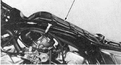
Loosen the :air cleaner connecting tube bands and remove the connecting tube.
Remove the screws and throttle linkage cover. Disconnect the throttle cables from the carburetor. Remove the choke cables from the carbu retor by loosening the. choke cable end nut.
(1lCONNECTING TUBE
(1) CHOKE CABLE
(2) TH ROTILE CABLES
Remove the ch oke valve and spring from the choke cable.
Check the choke valve and spring for nicks,grooves, or other damage.
VACUUM CHAM BER REMOVA L
Remove the four vacu um chamber cover screws and cover.
(1) (1) SPRING
(2)
.
Inspect the vacuu m piston for wear. nicks, scratches or other damage. Make sure the piston moves up and down f reel y in the chambet.
Push the needle holder in and tu m i t 60 degrees with an 8 mm sod<et. Then remove the needle holder, spring and needle from the piston.
Remove the plastic washer from the piston.
Inspect the needle for excessive wear at the tip and for bending, or other damage.
Check the diaphragm for deterioration and tears.
11) NEEDLE HOLDER
(0 DIAPHRAGM
r , :·\ 141 NEEDLE l31SPRING (2) NEEDLE HOLDER
INSTALLATION
Installation is essentially the reverse of removal. Install the chamber cover so that its. cavity aligns with the hole in the diaphragm.
FLOAT CHAMBER REMOVAL
Remove the four float chamber screws and the float chamber. (1) CAVITY
(2)
Measu re the float l evel with the carbu retor inclined 15°-45° from vertical and the f loat tang just coo tacing the float valve. ·. SPECIFICATION:6.8 mm (0.27 inl
(2) FLOAT LEVEL GAUGE 07401-0010000 fl) FLOAT LEVEL
FLOAT AND JETS
Remove the f loat pin, float and float valve.
Inspect the float valve for grooves and nicks. Inspect the operation of the float valve. ( llFLOAT PIN
Remove the main jet, needle jet holder and slow jet. R emove the float valve seat end filter. Inspect the float valve seat and filter for grooves, nicks or deposit$.
ASSEMB LY
Assemble the f loat chamber comp0nents in the reverse order of disassembly,
(1) MAIN JET
12)
CS) FILTER (6) SLOW JET
REMOVAL
NOTE
Remove the two screws and th rottle linkage cover.
CAUTION
Dam age to r he pilot screw s ur will occur if th e pilot s crew is tighten ed against th e se at.
Remove the pi lot screws and inspect them. Replace them if they are wom or damaged (page 4·12).
INSTALLAT ION
NOTE
CARBURETOR SEPAR ATION Loosen the synchronization adjusting screw and remove the spring_
Remove the screws attach ing the carbu retors together.
Carefully separate- the No. 1 and No. 2 carburetors. Remove the th ronl e l i n k th rust spring. Remove the fuel tu bes and T·f i tting.
Loosen the throttle stop screw.
Remove the nut attaching the th rottle drum and re· move the throttle dru m and return spring.
CARBURETOR ASSEMBLY Install the throttle retu rn spring, throttle drum and nut.
Tighten the nut se-curely.
(1 ) N UT
(2)
FUEL SYSTEM r:::iJ\ H O NDA VT500C
Connect the fuel line.
I nstall the th rust spring and engage the throttle l inks of the No. 1 and No. 2 carburetors.
Loosen the syrich ron ization adjusting screw until there is no tension.
Install the synch ronization spring.
Secure the carburetors together wi th the two attach· ing screws.
I nstall the carburetor ai r ven t tubes. (1) THRUST SPRING
(1) SPRING
(2) ADJUST ING SCREW
(1) SCREWS
Turn the throttle stop screw to align the No. 1 thronle valve with the edge of the by·pass hole.
Align the No. 2 throttle valve with the by-pass hole edge by turning the synchronization adjusting screw.
Inspect throttle operation as. described below: Open the throttle sl ghtly by pressing on the throttle linkage. Then release the throttle. Make sure that it returns smoothly. Make sure that there is no drag when opening and closing the throttle.
(1) HOLE (2) SYNCHRONIZATION ADJUSTING SCREW
CARBURETOR INSTALLATION
(2) SYNCHRONIZATION ADJUSTING SCREW
Perform the following inspections and adjustments. Thrott.le operation ( page 3·5). Carburetor choke (page 3·61. Carburetor synchronization (page 3·10). Carburetor idle speed (page 3·10).
FUEL SYSTEM PI LOT SCREW ADJUSTMENT IDLE DROP PROCEDURE
NOTE
1. Turn each pilot screw clockwise until it seats lightly and back it out to the specif ication given. This is an initial sening pr or to the final pilot screw adjustment.
INITIAL OPENING: No. 1 (Rear) 2·1/4 turns out No,2 (Front) 2·1/4 t11rm out
VT500C
2. Warm up the engine to operating temperature. Stop and go driving for 10 minutes is suff icient. 3. Attach a tachometer according to the manufac· turer's instructions. 4. . Adjust the idle speed with the throttle stop Screw. IDLE SPEED: 1,100 min-1 (rpm)
5. Turn each pilot screw 1/2 turn out from the initial setting. 6. If the engine speed increases by 50 rpmor more, turn each pilot screw out by a continual 1/2 turn until engine speed drops by 50 rpm or less. 7. Adj ust the idle speed with the throttle stop screw. 8. Turn the No. 1 carburetor pilot screw in until the engine speed drops 50 rpm. 9. Turn the No. 1 carburetor pilot screw 1 turn out from the position obtai1ned in step 8. FUEL S YS TEM VTSOOC 10. Screw. 11. Perform steps 8, 9 and 10 for the No. 2 car buretor pilot screw. 12. I nstall the throttle linkage cover.
/)() not allow {/4mes or Spal'ks near gasoline. Wipeup spille d gasoli n e ot once.
Check the vent hole of the f iller cap for blockage. Check that fuel is flowing out of the fuel valve using a vacu um pump. If fuel flow is restricted, clean the fuel strainer. NOTE
Do not overtighten the fuel valve lock nut.
(1)
(2) DIAPHR AGM
AIR CLEANER CASE
as any signs of deten.or aettioennora tion. Replace
CRANKCASE . Check that the br Ae os nIOotNreSstYriSctTedE.M VTSOOC
(2.0-2.4 kg.m, 14-17 ft-lb)
30-35 N·m (3.0-3.5 kg·m, 22-25 ft·lb)
45-60 N·m (4.5--0.0 kg-m,33-43 ft·lb) |
Последнее изменение этой страницы: 2019-06-10; Просмотров: 221; Нарушение авторского права страницы


 IQ
IQ


 loosen the carbu retor bands and remove the car buretors from the left side.

 CHOKE VALVE
 (2) COVER
 Remove the compression spring, diaphragm and vacu um pistol'I.

 4..
4..

 FLOAT CHAMBER
 FLOAT LEVEL


 NEEDLE JET HOLDER


 PI LOT SCREW
 Tum each pilot screw in and carefully count the number of tu rns before it seats lightly. Make a note of this to use as a reference when rei nstalling the pilot screws.

 Install the pilot screws and return them to thei r original position as noted duri ng removal. Perform pilot screw adjustment if new pi lot screws are installed ( page 4-12).


 {3) SCR EWS


 Installationis essentially the reverse of removal. NOTE
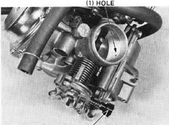
 (2) THROTTLE STOP SCREW


 ( 1) PILOT SCREW
 Adjus t the idle speed with the throttle stop
 FUEL TANK

 M ake sure there are no fue l le aks.
 LOCK NUT
 FU E L SYST E M
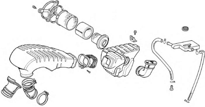
 20-24 N·m