
|
Архитектура Аудит Военная наука Иностранные языки Медицина Металлургия Метрология Образование Политология Производство Психология Стандартизация Технологии |
|
|
Архитектура Аудит Военная наука Иностранные языки Медицина Металлургия Метрология Образование Политология Производство Психология Стандартизация Технологии |
To the specified torque value.
TORQUE WRENCH SCALE READING: 80-100 N ·m (8.0-10.0 kg m, 58-72 ft·lb) ACTUAL TORQUE APPLIED: 90-110 N·m (9.0-11.0 kg·m, 65-80 ft·lb)
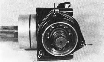
Attach the bearing holder onto the gear case with the three hex bol ts. Tigh ten tu bolts i n a crisscross pattern i n two or more steps.
TORQUE: 30-40 N·m (3.0-4.0 kg m, 22-29 ft·lbl
Install a new beari ng inner race lock nut and tighten it to the specified torque.
TORQUE WRENCH SCALE READING: 64-73 N·m (6.4-7.3 kg-m, 46-53 ft·lb) ACTUAL TORQUE APPLIED: 70-80 N·m (7.0-8.0 kg-m, 51-58 ft-lb) (1lLOCK NUT WRENCH 34 x 44 mm, 07916:-MESOOOO
(1) SHAFT HOLDER 07924-ME50000
(21LOCK NUT WRENCH , 34/44 mm 07916-MESOOOO
Stake both new lock nuts and install a new oil seal.
OUTPUT DR IVEN GEAR CASE BEARING REPLACEMENT
(1l STAKE (2)01L SEAL
(1) FIN AL DR I VEN SHAFT BEARI NG
(1) BEAR I NG REMOVER, 15mm
CRANKSHAFT/TRANSMISSION
Drive a new bearing into the output gear case.
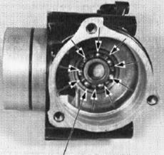
GEAR TOOTH CONTACT PATTER N CHECK
Remove the drive and driven gears ( pages 13·19, 13-22).
Apply Prussian Blue to the driven ar teeth.
Install the drive and driven gears with the standard shims.
Rotate the drive gear several times in the normal direction of rotation.
Check the gear tooth contact pattern af ter removing the drive gear. Con tact i s normal i f Prussian Bl ue is transferred to the approximate center of each tooth and sl ightly to the side.
R eplace the shim with a thinner one if the contact pattern is too high. H ONDA
(1 ) DR IVER 07749-0010000
(2) ATTACHMENT, 37 x 40 mm 07746-0010200
CRANKSHAFT/TRANSMISSION H ONDA VTSOOC
The pattern will shift about 1.5-2.0 mm (0.06- 0.08 in) when the thickness of the shim is changed by 0.10 mm (0.04 in).
OUTPUT DRIVEN GEAR ADJUSTMENT SHIM: A : 0.4 mm (0.016 in) 8: 0.46 mm (0.018 in) C: 0.5 mm (0.019 in) D: 0.66 m m (0.021 in} E: 0.6 mm (0.024 i n)
Check the back lash (See page 13-18).
OUTPUT DRIVE GEAR DAMPER ASSEMBLY INSTALLATION
I nstall the damper spring and damper cam onto the output drive shaft.
NOTE
Seat the damper spring against the bear ing lock nut.
Attach the spring compressor in the output drive shaft threads. Compress the damper cam with the special tool.
Install the circlip onto the shaft. being sure it seats in its groove. Loosen and remove the special tool from the shaft.
|
Последнее изменение этой страницы: 2019-06-10; Просмотров: 223; Нарушение авторского права страницы


 Heat the output gear case around the driven shaft bearing to B0°C (176°Fl and tap it out with a soft faced hammer.

 Remove the bearing with the bearing remover, if the bearing can not be removed by heating the case.
 I f the pattern is not correct, remove and repIace the driven gear adjustment shim.
 VTSO OC

 Pl LOT, 15 mm 07746-0040300


 Replace the driven gear adjustment shim with a th icker one i f the contact is too low.
