
|
Архитектура Аудит Военная наука Иностранные языки Медицина Металлургия Метрология Образование Политология Производство Психология Стандартизация Технологии |
|
|
Архитектура Аудит Военная наука Иностранные языки Медицина Металлургия Метрология Образование Политология Производство Психология Стандартизация Технологии |
B R AK E FLU ID REPLACEMENT / AIR BLEEDI NG
Check the f l uid level with the f lu id resevoi r parallel to the ground.
(1) ) LOWER LEVEL
B RAK E F LU I D D RA I N ING
Connect a bleed hose to the bleed valve.
Loosen the caliper bleed valve and pump the brake lever. Stop operati ng the lever when fluid stops f lowing out of the bleed valve.
BRAK E F LUI D F I L LI NG
NOTE
Do not mix different types of fluid since they are not compatible.
Close the bleed val ve, f i ll the reservoir, and i nstall the diaphragm.
Bleed the system as per the instruction on the next page.
(1) HYDRAULIC BRAKES VTSOOC
AIR BLEEDING
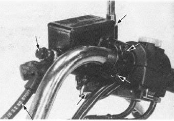
Check the fluid level often while bleeding the bra kes to prevent air from being pump ed i n to the system. Use only DOT 3 brake f lu id from a sealed contai ner. Do not mi x brake fluid types and never re use the contaminated f luid which has been pumped out dur ing bra ke bleed ing, because that wil l impair the efficiency of the brake system. When using a brake bleeding tool, follow the man ufacturer's operating instructions.
Connect a Mitvvac Brake Bleeder No. 6B60 or equivalent to the bleed valve. Loosen the bleed val ve 1/2 turn and bleed air u n ti l bubbles do not appear in the f l uid . Pump the brake lever or pedal to bri ng the caliper pads in contact with the disc. Remove the master cylinder cap and f il l the reser voir to near f ull. Connect the Mityvac Brake Bleeder or equiva lent to the bleed valve. Pump the brank bleeder and loosen the bleedi.r valve. Add fluid when the fl uid level in the master cylinder R eservoir i s low. Repeat the above procedu res until air bubbles do not appea r, in the plastic hose.
NOTE
I f a brake bleeder is not available, perf orm the following proced ure. 1) Sq ueeze the brake lever, open the bleed valve 1/2 turn and then close the valve.
2) Release the brake lever s'lowly and wait several seconds after i t reaches the end of i ts travel.
Repeat steps 1 and 2 until bubbles cease to appear in the f luid at the end of the hose . Fill the fluid reservoi r to the upper l evel mark .
(2)
 MITYVAC BR AKE BLEEDER OR EQUI VALE NT MITYVAC BR AKE BLEEDER OR EQUI VALE NT
(1)
BRAKE PAD / DI SC PAD R EPLACEMENT
NOTE
Always replace the brake pads i n P·airs to as· sure even disc pressure.
Remove the caliper shaft. mou nt bolt and caliper.
Remove the pad pin retai ner .
Pull the two retainer pad pi ns and remove the pads from the caliper.
(1) PAD PIN R ETAINER
(1)
HYDRAULIC BRAK ES VTSOOC Position the pad spring i n the caliper as shown. Push the caliper pistons i n all the wav .
Instal l the new pads i n the caliper.
Install the pad pins, one pad pi n fi rst, then install the other pin by pushing the pads against the caliper to depress the pad spring.
Place the pad pi n retainer over the pad pi ns. Push the retai ner down to secure the pins.
Install the pad pin retainer bolt.
(2) A ETAINEA
TORQU E: CALIPE R SHAFT: 250 N·m (2.5-3.0 kg·m, 18-22 ft-lb} MOUNT BOLT: 20-25 N·m (2.0-2.5 kg m, 14-18 ft-lb}
DISC THICKNESS
Measure the thickness of disc.
SE RVICE LIMIT: 4.0 mm (0.16 in}
BRAKE DISC WA RPAGE
Set the brake disc on a surface plate and set up a dial indicator. Measure the brake disc warpage.
SERVICE LIMIT: 0.30 m m (0.012 in) pr;( MA S TER C YLINDE R DISASSEMBLY
Drain brake fluid from the hydraulic system.
Remove the brake lever and rear view mirror from the master cylinder. Disconnect the brake hose.
CAUTI O N
(1) BRAKE HOSE
Remove the master cylinder.
{
Remove the brake light switch from the master cylinder body, if necessary .
Clean the inside of the master cylinder and reservoir with brake fluid.
(1) SNAP RING PLIERS 07914-3230001
Measure the master cylinder 1.0.
SE RVICE LIMIT: 15.93 mm (0.627 in)
Check the master cylinder for scores, scratches or nicks.
Measure the master piston 0.0.
SERVICE LIMIT: 15.82 mm (0.623in)
Check the primary and secondary cups for damage before assembly.
CAUTION
Assemble the master cylinder . Coat all parts with clean brake f luid before assembly. Install the spring and pri mary cup together.
Dip the piston cup in brak.e fluid before assembly.
CAUTION
Install the piston clip and !boot.
Place the master cylinder on the handlebar and install the holder with the two mounting bolts. Tighten the top bolt first. Then the bottom bolt.
TOR QUE: 10-14 N·m (1.0-1.4 klt'm. 7-10 ft·l b)
Install the oil hose wi th the bolt and its two sealing washers. Tigh ten the bolt.
TOR QUE:25-35 N·m (2.5-3.5 kg m.18-25 ftb)
Install the brake lever.
Fill the reservoir to the upper level and bleed the brake system according to page 17-4.
REMOVAL
Place a clean container under the caliper and dis· connect the brake hose from the caliper.
CAUTION
A void s pilling bro ke flui d on painted surfocn . Remove the caliper shaft.mou nt bolt and caliper.
DISASSEMBLY
Remove the following: - pads and pad spring. - caliper pivot collar and boots. - pistons from the caliper. (11PUNCH MAR K
(3) PAO SPRING (4J BOOTS
Examine the pistons and cylinders for scoring, scratches or other damage and replace if necessary.
CAUTION
PISTON INSPECT ION
Check the pistons for scoring, scratches or other faults. Measure the piston diameter with a micro· meter.
SERVICE LIMIT:30.14 mm (1.187 in) (1)PISTON SEALS
CYLINDER INSPECTION
Check the caliper cylinder bore for scoring, scratches or other faults. Measure the caliper cylin der bore.
SERVICE LIMIT: 30..29 m m (1.193in)
ASSEMBLY
If the piston boots are hardened or deteriorated. re· place them with new ones. The piston seals must be replaced with new ones whenever they are removed. Coat the seals with si licone grease or brake fluid before assembly.
Install the pistons with the dished ends toward the pads . Then install the piston, boots.
I nstall the collar boots and collar mak ing sure that the boots are seated in the collar and caliper groove proper ly.
I nstal I the pad spring and pads.
INSTA LLATION
Instal l the caliper, shaft and moun ti ng bolt. Tigh ten the shaft and bolt to the speci·fied torque.
TORQUE: CALIPER SHAFT: 25-30 N·m (2.5·-3.0 kg-m, 18-22 ft-lb) CALIPE R MOUNT: 20-25 N·m (2.0-2.5 kg-m, 14-18 ft-lb)
I nstall the brake hose wi th the bolt and sealing was hers.Tighten the bolt.
TORQUE: 25-35 N-m (2.5-3.5 kg nn, 18-25 ft lb)
Fi ll the brake f l uid reservoir and bleed the front brake system {page 17-3).
(4) OI L SEALS
(5)
(2) MOU NT BOLT
(6) COLLAR
FRONT CALIPER BRACK ET DISASSEMBLY
Remove the brake caliper ( page 17·5).
Remove the caliper mount bolts and remove the caliper.
Remove the two caliper bracket mount bolts and remove the caliper bracket.
Remove the boot and the pad spring from the cali· per bracket, maki ng sure that th ey are in good condition.
FRONT CALIPE R BRACKET ASSEMBLY
Install the boot and the pad spring.
Attach the cal i per bracket to the front fork.
TORQUE: 30-40 N·m (3.0-4.0 kg-m , 22-29 ft·lb) Install the lrunl caliper (page 17-12). (1J CALIPER BRACKET MOUNT BOLTS
(1)
·· o
• • • l'l - BOT/WEISS HAUPTSICHEAUNG
AOT - !!:! -a:
;;: 0 J ...J w >-
- f- - m
LICHTMASCHINE ' • • l . ' SCH \ " I C GRON -- REGLER/GLEICHRICHTER
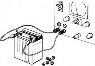
BATTERY REMOVA L
Disconnect the negative terminal lead from the battery first, then disconnect the positive t.erminal lead. Disconnect regulator/rectifier coupler and the battery tube and pull out the battery.
TESTI NG SPECIFIC GRAV ITY
Test each cel l with a hydrometer .
SPECIFIC GRAVITY: 1.270-1.290 at 20°C (68°Fl VTSOOC
CHARG ING Remove the battery cell caps. Fill the battery cells with distilled water to the upper level line, ii neces s;ary. Connect the charger positi ve (+) cable to the battery positive (+) terminal. Connect the charger negative (-) cable to the battery negative (-) terminal. Charging current: 1.6 amperes max. Charge the battery unti l specif ic gravitY is 1.270- 1.290 at 20°C (68°F).
After installing the battery, coat the terminals with clean grease.
CHARGING SYSTEM CUR R ENT TEST NOTE
Be sure the battery is in good condition before performing th is tes<.
j2 lPIPING AS SHOWN BELOW.
1 - (4) BATTERY BR E ATHER TUBE 5> TUBE CLAMP
1s1 INSERT THE BATTERY BREATHER TUBE SECURELY
Remove the seat.
Disconnect the alterna tor coupler.
Check f or contin ui ty between the leads, and be· tween the leads and ground. Replace the stator if there is no contin uity between the leads, or i f there is con tinuity between the leads and grou nd.
TEST Remove the seat. Disconnect the regula tor/rectifier couplers.
Check for continuity between the leads with an ohm meter.
NOT E
z Q ..... () w a: a ..J <( :E a: 0z
3: 0 ..J ..J w >
(41GR EEN
z
w a: a w Va>: w w> a: @
|
Последнее изменение этой страницы: 2019-06-10; Просмотров: 205; Нарушение авторского права страницы


 To prevent piston overtravel and brake fluid see· page, keep a 20 mm (3/4 i n) spacer between the handlebar grip and lever when f illing and bleed ing the front brake system. Pu mp up the system pres· sure with the lever until there are no air bubbles in the fluid flowing out of the reservoi r small hole and lever resistance is felt.
 20 mm (3/4 I N ) SPACER
 NOTE
NOTE


 UPPER LEVE L


 PAD PINS


 ( 1) PAO PI NS


 Remove the piston boot and the circlip from the master cylinder body.
 Remove the secondary cup and piston.Then remove the primary cup and spring.
 INSPECTI ON
 BRAKE CALIPER
 ASSEMBLY


 (1 ) PISTONS (2) PIVOT COLLAR
 If necessary , apply compressed air to the caliper f l uid inlet to get the piston out. Place a shop rag under the caliper to cushion the piston when it is expelled.Use the air i n shor t spurts.
 Push the piston seal s i n, lift them out and discard them.
 Clean the oil seal grooves with brake f luid.
 -
-
 (2)
(2) (1)PISTONS PISTON BOOTS (3) BOOTS
 PAD SPRING


 BOOT
BOOT
 REGLER/GLEICHRICHTER

 30A
30A

 BATTERY/CHARGING SYSTEM

 NOTES
NOTES (41 Specific gravity changles by 0.007 for every 1o"C.


 !3lBATTER Y ELBOW
 MF5-300

 STATOR CONTINUITY TEST
 VOLTAGE REGULATOR/R ECTIFIER

 (31R ED/WH ITE
