|
Архитектура Аудит Военная наука Иностранные языки Медицина Металлургия Метрология Образование Политология Производство Психология Стандартизация Технологии |
|
|
Архитектура Аудит Военная наука Иностранные языки Медицина Металлургия Метрология Образование Политология Производство Психология Стандартизация Технологии |
Theme 3. The basic laws of kinematics and fluid dynamics.Стр 1 из 3Следующая ⇒
LECTURE № 3
Theme 3. The basic laws of kinematics and fluid dynamics.
Questions. 1. Basic concepts and definitions. 2. Consumption. 3. The equation of continuity of a flow.
HYDRODYNAMICS studies the laws of fluid motion and interaction with washing bodies. The cause of motion is the action of forces on the liquid. The main parameters characterizing the movement are internal pressure and velocity at individual points. The pressure is called hydrodynamic. In the general case, velocity and pressure are functions of the coordinate and time. The task of hydrodynamics is to study the interaction between velocity and pressure at individual points. Types of movement
Unsteady is the most general case of motion. p and u depend on the coordinate and time p = f (x, y, z, t), u = g (x, y, z, t). The steady-state - p and u do not depend on time, i.e. p = f (x, y, z), u = g (x, y, z) or dp / dt = 0, du / dt = 0.
Uniform - speed, and in some cases, the pressure does not change along the flow. Thrust, free movement and free streams
Trajectory, streamline, elementary trickle. The trajectory is the trace of a moving particle.
The current tube is an elementary site, through which the current lines are drawn. Elementary trickle is a part of the liquid bounded by the tube of current. Set of lines of current passing through the elementary area. An elementary trickle has the following properties:
1. the shape of the elementary trickle remains unchanged in time. 2. The exchange of particles between individual streams is not possible (the velocity vector is directed along the tangent, the normal component is 0). 3. The velocity and pressure at all points of the section are identical in view of the smallness of the cross section. Flow The aggregate of elementary streams flowing through the area is large enough, but of limited dimensions. When studying the flow, consider a smoothly changing motion and a drastically changing motion. In the future, we will consider only a smoothly changing motion. Smoothly changing motion is a movement that is close to a parallel jet movement. Properties: 1. The curvature of the current line is negligible, i.e. the radius of curvature tends to infinity. 2. The angle forming the streamlines is close to 0. 3. The flow cross-section is flat normal to the flow axis. 4. The pressure within the section is subject to the laws of hydrostatics.
Flow Elements The area of the live section is the area of a flat cross-section normal to the direction of motion.
Hydraulic radius - the ratio of the area of the living section to the wetted perimeter R = w / c `For a circular section, R = p r2 / (2 p r) = r / 2 = d / 4. The equation of continuity Considering that 1. penetration of fluid through the side surface is impossible (because the surface is formed by current lines) 2. The liquid is incompressible 3. The liquid is a continuous medium (there are no discontinuities) can be written u1d w 1dt = u2d w 2dt Q = const u1/u2 = d w 2/d w 1 v1/v2 = w 2 / w 1 MEASUREMENT OF FLOW VOLUME-type flowmeters. To account for the amount of liquid consumed by individual small consumers (residential and public buildings, small businesses, individual shops), mechanical speed water meters are the most widely used. According to the design, high-speed (tachometric) liquid counters are divided into two main groups: winged, whose axis of rotation is perpendicular to the direction of movement of the fluid, and turbine, in which the axis of rotation of the turbine is parallel to the direction of movement of the liquid. The principle of action of high-speed liquid meters is based on measuring the number of revolutions of the impeller or impeller, driven by the flow of liquid flowing through the counter. The speed of the impeller or impeller is proportional to the amount of liquid flowing through the counter. The axis of the impeller or turbine is connected to the counting mechanism by means of a transmission mechanism, which, taking into account the number of revolutions, shows the amount of liquid flowing through the counter. Qmax is the maximum flow rate at which the meter can work for a short time, no more than one hour per day; Qnom is the nominal flow rate at which the meter can run for a long time; Qo is the operating flow rate at which the meter can operate continuously throughout the life of the device; Qmin - the lowest consumption, for which the limit of the permissible relative error is normalized; Qth.s. - threshold of sensitivity, such a smallest flow rate, at which the steady rotation of the meter working part begins.
Venturi nozzles and nozzles
The accuracy of the nozzle flow measurement is slightly higher than the accuracy of the diaphragm measurement due to the absence of an additional error in the insufficient sharpness of the input edge. Nozzles as narrowing devices for flowmeters have not received the spread, since the head loss in them is little less than in the diaphragms, and making them is much more complicated. A narrowing device with a high accuracy of flow measurement and not creating large head losses is the Venturi nozzle. A venturi nozzle is a tapering device whose inlet part is made in the shape of a standard nozzle, and there is a cone in the mouth that serves to reduce head losses. Depending on the length and the central angle of the cone, long and shortened Venturi nozzles are distinguished. In water supply and sewage systems, short venturi nozzles are more often used. Venturi nozzles are made of two types (Figure 2.4). The first type is designed for pipes with a conditional pass from 50 to 200 mm, performed with a nozzle made of non-ferrous metals and cast-iron housing. The second type is designed for pipes with a conditional pass from 250 to 1400 mm, performed with a cast iron nozzle, coated with an anticorrosive body without flanges. When installing the Venturi nozzle, the alignment of the pipe and the nozzle must be observed. There should be no sources near the Venturi nozzle, leading to distortion of the flow.
Venturi tubes were proposed earlier than other narrowing devices. Depending on the size of the diffuser, the Venturi tubes are short and long. There are three design versions of Venturi pipes: A - steel welded from sheet material at Du = 200... 1400 mm, Roux up to 16 MPa; B - with cast unprocessed input parts, processed with a neck at Du = 100... 800 mm Rouge up to 25 MPa; B - with treated inlet nozzle, cone and neck at Du = 50... 250 mm, Rouge up to 4 MPa.
The standard Venturi tubes (Figure 2.5) consist of the following main parts: the inlet cylinder, the tapering cone, the neck, the expanding cone and the output cylinder. All parts are assembled by welding. The pressure is taken from the averaging annular chambers. In the lower part of the annular chambers, cork valves are installed for draining the liquid. Venturi pipes are connected to steel pipelines by welding. In some cases, flanges can be connected. A feature of standard Venturi pipes is their small metal capacity. The necessary lengths of straight sections in front of Venturi tubes are substantially Construction of rotameters According to the design, the rotameters are divided into glass with a local reference (PM) and metal with an electrical (RE) or pneumatic (RP) output signal. Rotameters of the RM type with a glass tube (Figure 3.3) replace the formerly produced PG type.
Advantages of rotameters include comparatively small head losses (D h? 1 m), which depend little on the flow rate: for example, when the flow rate is changed by a factor of 5, the head loss increases by a factor of 1.5.2. Control questions. 1. To which group of flowmeters are rotameters? 2. What forces act on the float? 3. How will the pressure difference change if the weight of the float is increased? 4. How will the pressure difference change if the weight of the float is reduced? 5. How will the position of the float change if its weight is reduced and the flow rate is kept constant?
Fig. 3.4. Metal rotameters RE: a) for small flow; b, c) for large and medium flow 1. How will the position of the float change if its weight is increased and the flow rate is kept constant? 2. What explains the horizontal plot on the calibration schedule? 3. How will the horizontal section on the calibration chart change if the weight of the float is increased? 4. How will the angle between the calibration curve and the horizontal line change with increasing float weight? In what units is the scale of the glass rotameter scaled? LECTURE № 3
Theme 3. The basic laws of kinematics and fluid dynamics.
Questions. 1. Basic concepts and definitions. 2. Consumption. 3. The equation of continuity of a flow.
HYDRODYNAMICS studies the laws of fluid motion and interaction with washing bodies. The cause of motion is the action of forces on the liquid. The main parameters characterizing the movement are internal pressure and velocity at individual points. The pressure is called hydrodynamic. In the general case, velocity and pressure are functions of the coordinate and time. The task of hydrodynamics is to study the interaction between velocity and pressure at individual points. Types of movement
Unsteady is the most general case of motion. p and u depend on the coordinate and time p = f (x, y, z, t), u = g (x, y, z, t). The steady-state - p and u do not depend on time, i.e. p = f (x, y, z), u = g (x, y, z) or dp / dt = 0, du / dt = 0.
Uniform - speed, and in some cases, the pressure does not change along the flow. |
Последнее изменение этой страницы: 2019-04-10; Просмотров: 247; Нарушение авторского права страницы
 Depending on the change in the basic parameters p and u, two types of motion are distinguished: steady and unsteady.
  Steady motion can be uniform and uneven.
  Thrust is the motion of fluid on all sides bounded by solid walls.
 Free movement - part of the perimeter of the liquid is not limited to solid walls, i.e. there is a free surface.
 Free streams - the flow is not limited by the walls.
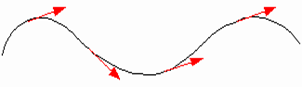 The current line is a line at each point of which the velocity vector is tangential. With steady motion, the stream line coincides with the trajectory of the moving particle.
 The wetted perimeter is part of the perimeter on which the stream contacts the solid walls.


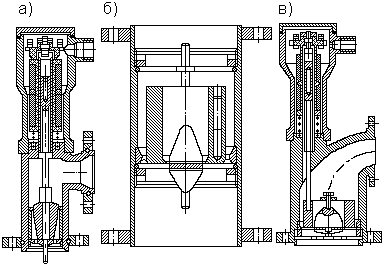
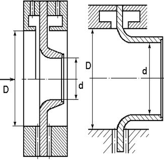 The basic equation of flow (2.3) is also valid for nozzles. The flow nozzle (Figure 2.3) is a device with a circular hole having a smoothly tapered part at the inlet and a cylindrical part at the outlet.
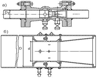 Venturi tubes
 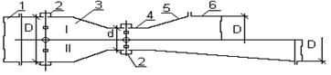 The most simple and convenient to manufacture are welded Venturi pipes.
 The float of the RM rotameters, depending on the measuring range, is made of steel, anodized duralumin, ebonite or titanium. Rotameters of this type can operate at a temperature of the medium to be measured between 5 and 50 ° C. They are widely used in scientific research, as well as in the industry for measuring small flow rates of liquids and gases (for example, in LONIISTO chlorinator). The main maximum reduced error is ± 2.5%.