|
Архитектура Аудит Военная наука Иностранные языки Медицина Металлургия Метрология Образование Политология Производство Психология Стандартизация Технологии |
|
|
Архитектура Аудит Военная наука Иностранные языки Медицина Металлургия Метрология Образование Политология Производство Психология Стандартизация Технологии |
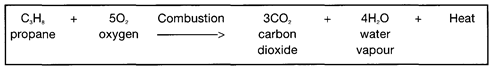
Figure 2.16 Mollier diagram for propane
by the saturated liquid line and the saturated vapour line which meet at the apex which is the critical point. As will be seen, the diagram also contains lines of constant temperature, constant volume, constant entropy and dryness fraction. Reliquefaction Superimposed on the Mollier diagram is an example of the pressure and enthalpy changes taking place in a simple shipboard reliquefaction cycle. This covers the boil-off from a semi-pressurised cargo of propane being carried at 3 bars and -14°C. (In following this example reference can also be made to 2.11 and Figure 2.8.) At A on the diagram, the boil-off vapour is drawn off from the cargo tank and compressed to 10 bars at B. It is generally assumed that the compression is adiabatic; that is with no heat lost from the vapour during the compression (see also 2.14). For such an ideal adiabatic process, the change in entropy is zero and the line AB follows a line of constant entropy. The difference in enthalpy between B and A (approximately 840 — 790 = 50 kJ/kg) represents the work input to the vapour by the compressor. It will also be noticed that the line AB crosses lines of constant volume; this indicates decreasing volume due to compression. From B to C, the vapour has heat taken from it and is condensed to liquid. The position of C in this example shows that the condenser has achieved some degree of sub-cooling of the liquid. The enthalpy change from B to C (approximately 840 — 470 = 370 kJ/kg) represents the heat removed by the condenser. The liquid condensate is then expanded through a regulating valve (expansion valve) and returned to the ship's tank at a pressure of 3 bars. In this procedure, the condensate neither gives up nor receives heat and thus there is no change in enthalpy. In the expansion process, the change in sensible heat (cooling) exactly matches the ingress of latent heat required for flash evaporation. The line CD is, therefore, vertical and the position of D indicates a dryness fraction of 0.2 for the returned condensate: that is 20 per cent mass of vapour and 80 per cent mass of liquid. The total refrigeration effect of the cycle is given by the difference in enthalpy of the vapour drawn to the compressor at A and that of the condensate return at D (approximately 790 — 470 = 320 kJ/kg). FLAMMABILITY Combustion Combustion is a chemical reaction, initiated by a source of ignition, in which a flammable vapour combines with oxygen to produce carbon dioxide, water vapour and heat. Under ideal conditions the reaction for propane can be written as follows: —
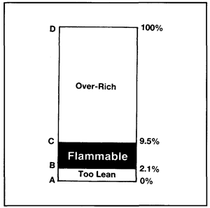
Under certain circumstances when, for example, oxygen supply to the fuel is restricted, carbon monoxide or carbon can also be produced. The three requirements for combustion to take place are fuel, oxygen and ignition. Furthermore, for ignition to occur, the proportions of vapour to oxygen (or to air) must be within the product's flammable limits. The gases produced by combustion are heated by the reaction. In open spaces, gas expansion is unrestricted and combustion may proceed without undue over-pressures developing. If the expansion of the hot gases is restricted in any way, pressures will rise and the speed of flame travel will increase. This depends upon the degree of confinement encountered. Increased flame speed gives rise to a more rapid increase in pressure with the result that damaging over-pressures may be produced. Even in the open, if the confinement resulting from surrounding pipework, plant and buildings is sufficient, the combustion can take on the nature of an explosion. In severely confined conditions, such as within a building or ship's tank, where the expanding gases cannot escape, the internal pressure and its rate of increase may be sufficient to burst the containment. Here, the explosion is not due to high combustion rates and flame speed: it results more from the surge of high pressure upon containment rupture. The BLEVE A BLEVE (Boiling-Liquid/Expanding-Vapour Explosion) is an explosion resulting from the catastrophic failure of a vessel containing a liquid significantly above its boiling point at normal atmospheric pressure. The container may fail for any of the following reasons: mechanical damage, corrosion, excessive internal pressure, flame impingement or mettalurgical failure. The most common cause of a BLEVE is probably when a fire increases the internal tank pressure of the vessel's contents and flame impingement reduces its mechanical strength; particularly at that part of the vessel not cooled by internal liquid. As a result, the tank suddenly splits and pieces of the vessel's shell can be thrown a considerable distance with concave sections, such as end caps, being propelled like rockets if they contain liquid. Upon rupture, the sudden decompression produces a blast and the pressure immediately drops. At this time the liquid temperature is well above its atmospheric boiling point and, accordingly, it spontaneously boils off, creating large quantities of vapour which are thrown upwards along with liquid droplets. Where the gas/air mixture is within its flammable limits, it will ignite from the rending metal or the surrounding fire to create a fireball reaching gigantic proportions and the sudden release of gas provides further fuel for the rising fireball. The rapidly expanding vapour produces a further blast and intense heat radiation. Such BLEVE incidents have occurred with rail tank cars, road vehicles and in a number of terminal incidents. There have been no instances of this kind on liquefied gas carriers. Under the Gas Codes, pressure relief valves are sized to cope with surrounding fire and, as for shore tanks, this helps to limit this risk. It must be said that the chance of a fire occurring in the enclosed space beneath a pressurised ship's tank is much smaller than on an equivalent tank situated on shore. This minimises the possibility of a surrounding fire occurring on a ship and almost excludes the possibility of a BLEVE occurring on a gas carrier. Flammable Range The concept of a flammable range gives a measure of the proportions of flammable vapour to air for combustion to occur. The flammable range is the range between the minimum and maximum concentrations of vapour (per cent by volume) in air which form a flammable mixture. The lower and upper limits are usually abbreviated to LFL (lower flammable limit) and UFL (upper flammable limit). This concept is illustrated for propane in Figure 2.17.
|
Последнее изменение этой страницы: 2019-06-09; Просмотров: 237; Нарушение авторского права страницы