|
Архитектура Аудит Военная наука Иностранные языки Медицина Металлургия Метрология Образование Политология Производство Психология Стандартизация Технологии |
|
|
Архитектура Аудит Военная наука Иностранные языки Медицина Металлургия Метрология Образование Политология Производство Психология Стандартизация Технологии |
EN G INE R E MO VAL/I N STA LLA T I ON
VTSOOC
Place the motorcycle on its center stand. Remove the seat and fuel tank. Remove the left and righ t frame side covers.
Drai n the engine oil (page 2-3) and the coolant (page 6-3).
(2) SIDE COVER
Remove the radiator (page 6-6).
Remove the rear brake pedal.
Remove the exhaust pipe flange nuts.
Loosen the exhaust pipe clamp bolts and remove the exhaust pipes.
(1) RADIATOR
(1) BRAKE PEDAL
(2) CLAMP BOLT (3) EXHAUST PIPE
Loosen the muffler clamp bolts and remove the muffler mount bolts.
Remove the mufflen;.
Remove the power chamber mounting bolts and power chamber.
Disconnect the alternator and neutral/OD switch wire coupler (page 1 10).
Remove the air cleaner connecting tube and car· buretor (page 4·3).
Disconnect the tachometer ca'ble from the engine. Remove the spark plug caps.
(1) MUFFLER (2) POWER CHAMBER
(1) TACHOMETER
E N G INE RE MOV AL / IN S T A LL A11'10 N Disconnect the water hoses from the cylinder head. Disconnect the crankcase breather tube. Disconnect the pulse generator wi re coupler.
Remove the left crankcase rear cover. Remove the gear shift arm pinch bolt. Remove the left footpeg mounting bolts. Remove the left foo1pe9 and mhifl linkQge s a set. VT500C
(1) WATER HOSE WIRE COUPLER
(1) GEARSHI FT(2)GEARSHI FT
(4) GEARSHIFT PEOAL (51LEFT FOOT PEG {6)LEFT CRANKCASE REAR COVER
Rem ove the brake pedal pivot.
Discon nect the clutch cable by loosening the h andle bar adjuster. Disconnect the starter motor cabl e.
Ploce a floor jack or other adjustable support unde r the engine.
NOTE
(1)
(2) STARTER MOTOR CABLE
(1) ENGINE HANGER BRACKET
Remove the engine moun ting bolts.
Remove th e engine from the right side while dis· connecting the drive shaft universal joint from the engine.
Engine installation is essentially the reverse of re· moval. Use a floor jack or other adjustable support to carefully manuever the engine into place.
CAUTION
Tighten the all fasteners to the specified torque:
ENGINE MOUNT BOLTS: 8 mm BOLT: 20-30 N·m (2.0-3.0 kg·m,14-22 ft-lb) 10 mm BOLT: 45-60 N·m (4.5-6-.0 kg-m,33-43 ft-lb) SUB-FRAME MOUNT BOL.T AND NUT: SOCKET BOLT: 30-35 N·m (3.0-3.5 kg-m,22-25 ft-lb) FLANGE NUT: 20-24 N·m (2.0-2:.4 kg·m, 14-17 ft-lb)
Install the rear cylinder exhaust pipe to the chamber bolt loosely. Install them to the flame.
EXHAUST PIPE JOINT NUT: 8-14 N·m (0.8-1.4 kg-m,6-10 ftlb) EXHAUST PIPE CLAMP BOLT: 20-28 N·m (2.0-2.8 kg-m,14-20 ft-lb) MUFFLER CLAMP BOLT: 20-28 N·m (2.0-2.8 kg-m, 14-20 ft-lb)
COOLING SYSTEM H ONDA VT500C
SYSTEM TESTING COOLANT
Test the coolan t mixture with an anti-freeze tester. For maximu m corrosion protection, a 50-50% solu tion of ethylene glycol and distilled water is recom mended .
RADIATOR CAP INSPECTION
Pressure test the radiator cap. Replace the radiator cap if i t does not hold pressure, or if relief pressure is too high or too low. I t must hold specified pres sure for at least six seconds.
NOTE
Before installing the cap on the tester, apply water to the sealing surfaces.
RADIATOR CAP RELIEF PRESSURE: 73.6-103.0 kPa (0.75-1.05 kg/cm 2 , 10.7-14.9 psi)
CAUTION
Repai r or replace components if the system wi ll not hold speci fied pressure for at least six seconds.
(2) COOLING SYSTEM TESTER
COOLING SYSTEM
COOLA NT REPLACEM ENT CAUTION
T he engine must be cool before ser11icing the coo/Ing system, orsevere scalding may result. Remove the fuel tank rear moun ting bolt and raise the f ront of the fuel tank.
Remove the steering stem cover. Remove the radiator f iller cap.
Remove the drain bolt located at the water pump and drain the system coolant.
Reinstall the sealing washer and bolt.
Loosen the air bleed bolt located at the l eft of the thermostat housing.
Fill the system with a 50-50 mixture of disti lled water and ethylene glycol.
Reti\jlten the bleed bolt. r::tiJ\ H O NDA
(1) DRAIN BOLT WITH SEALING WASHER
• Start the engine and let it ru n un til there are no air bubbles in the coolan t, and the level sta- bilizes. Stop the engine and add coolant u p to the proper level if necessary. R einstall the radiator cap. Check the level of coolant in the reserve tank and f ill to the correct level i f i t is low. (2) BLEED BOLT
REMOVAL
Turn the fuel valve OFF. Remove the seat and fuel tank. Remove the coolant drain bolt, and drain the coolan t (page 6 3).
Loosen the water hose clamps.
RemOYe the air cleaner connecting tube.
(2) CLAMPS
RemOYe the steering stem covers. Remove the turn signal relay. Disconnect the temperature sensor wire.
Disconnect the overflow tube from the radiator filler neck.
Loosen the ignition coil bracket mou nti ng bolts.
Loosen the radiator hose clamp.
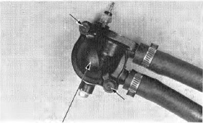
Remove the bolt attaching 'the therm0stat housing and filler neck.
Remove the thermostat housing and filler neck.
Remove the two bolts and thermosta t cover. (1) FILLER NECK MOUNTI NG BOLT (2)TURN SIGNAL R ELAY (3) OVER FLOW TUBE
(4) IGNITION COIL BRACKET (5) CLAMP (6) THERMOSTAT MOUNTI NG BOLTS HOUSI NG MOU NTI NG BOLTS
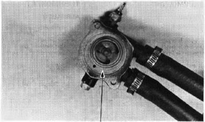
(1 l COVER
Remove the thennostat from the housing.
INSPECTION
Visually Inspect the thermostat for damage. Suspend the thermostat in heated water to check Its operation. Do not let the thrmostat or thermo meter touch the pan or false readings will result.
Replace the thermostat if the valve stays open at room temperature, or if it responds at temperatu res other than those specified.
Technical Data
INSTALLATION
Install the thermostat in the housing.
Install a new 0-ring onto the cover, place the cover onto the housing and tighten the bolts.
(!)THE R MOSTAT
(1) 0-R ING
(2) THERMOSTAT
COOLING SYSTEM
Install a new O·ring onto the fit ler neck.
lnuall the thermostat housing in the frame and install the filler neck.
Loosely, tigh ten the thermostat housing mounting bol ts.
Tigh ten the filler neck mounting bolt securely to the Ignition coil bracket
Tigh ten the Ignition coil bracket bolts. Tighten the water hose clamp bol ts. Con nect the temperatu re sensor wi re to the tempera· ture sensor.
Add coolan t In the system (page S.3).
I nstall the air cleaner connecting tube and fuel tank. Install the steering stem cover.
|
Последнее изменение этой страницы: 2019-06-10; Просмотров: 208; Нарушение авторского права страницы

 EN G INE REMOVAL


 CABLE (2)CAR BURETOR
 (2) PULSE GENERATOR
 LINKAGE ARM (3) PINCH BOLT
 Remove the rear wheel (page 16-3). Remove the final gear case {page 14-3).
 BRAKE PEDAL PIVOT
 Remove the righ t sub·frame. Remove the engine hanger bracket.
 ENG INE INSTALLATIO N
 NOTE
NOTE Install the remaining exhaust pipe and mufflers. NOTE


 Pressu rize the radiator, engine and hoses, and check for leaks.


 VTSOOC

 Bleed air from the radiator.
 THERMOSTAT