
|
Архитектура Аудит Военная наука Иностранные языки Медицина Металлургия Метрология Образование Политология Производство Психология Стандартизация Технологии |
|
|
Архитектура Аудит Военная наука Иностранные языки Медицина Металлургия Метрология Образование Политология Производство Психология Стандартизация Технологии |
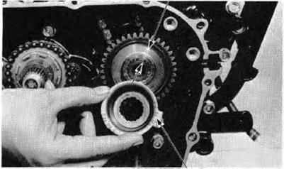
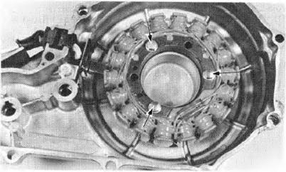
R IG HT CRANKCA SE COVER I NSTALLATI ON
Remove the gear holder tool and install the clutch. (1) PR IMARY GEAR
(2) PULSE GENE R ATOR PLATE
(2) OOWEL PINS
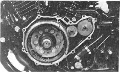
Ins tall the r igh t c ra nkcase cove r a nd t ight e n the cover bolts.
TORQUE: 8-12 N·m (0.8-1.2 kg m.6-9 f t-l b)
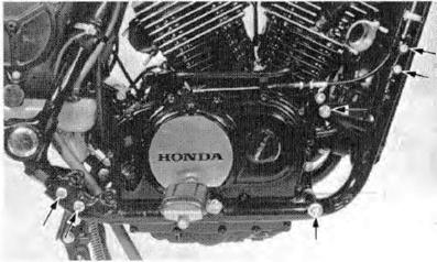
I nstall the sub-frame and ti ghten the bolts.
TORQUE : Upper: 30-35 N·m (3.0-3.5 kg-m, 22-25 ft-lb) Lower: 20-24 N·m (2.0-2.4 kg-m, 14-17 ft-lb)
Install and torq ue me engine mount nuts.
TORQUE: 45-·60 N·m (4.5-6.0 kg•m, 33-43 ft lb)
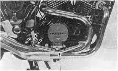
Install the exhaust pipe (page 5-6). Install the brake pedal shaft bracket. I nstall the brak e pedal.
Fill the crankcase with oil (page 2-3).
BRAKE PEDAL
ALTERNATOR/STARTER CLUTCH VT500C
8-12 N·m (0.8-1.2 kg-m, 6-9 ft-lb)
130-140 N·m (13.0-14.0 kg-m, 94-101 ft·l b)
Remove tho seat. Disconnect the al ternator cou pler.
Remove the rear cover. Remove the left foot peg and gear shift pedal.
Remove the alternator cover bolts and cover. Remove the gasket and dowel pins.
(2) GEAR SHIFT PEDAL (1) REAR COVER
ALTERNATOR / S T A R TE R CLUTCH H O NDA. VT500C
R emove the stator mounting bolts and stator from the alternator cover.
Hold the flywheel wi th the flywheel holder and remove the flywheel bol t.
NOTE
(2) FLYWHEEL HOLDER 07923-MESOOOO
Remove the flywheel wi th the rotor puller.
(1) ROTOR PU LLER
(2) FlYWHEEL
ALTERNATOR /STARTER CLUTCH
STARTER CLUTCH DI S ASSEMBLY Remove the flywheel (page 8-3).
Remove the s.tarter drive and reduction gears, and gea r shafts.
Pull the starter driven gear toward you un til i t stops.. Then remove the needle bearing from the gear.
Remove the driven gear. H ONDA VT500C (2)
(4) STARTE'A DR IVEN GEAR (5) GEAR SHAFTS
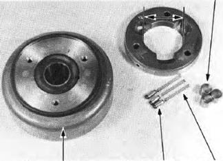
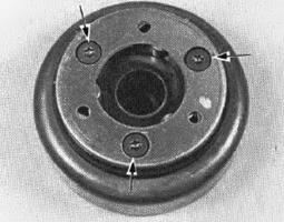
Remove the three ton< bolts attaching the starter clutch to the flywheel and remove the starter clutch and clutch outer.
STARTER CLUTCH INSPECTION
Inspect the starter clutch for smooth operation. Check the rollers for excessive wear. Measure the starter clutch outer l.D.
SER VICE LIMIT:70.96 mm (2.794 in)
(1) ROLLER
(2) IF LYWHEEL (3) PLUNGE R (4)SPRING
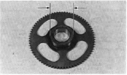
Measure the driven gear 0.0.
SER VICE LIMIT:54.06 mm (2.128 in)
STARTER CLULCH A S SEMBLY Install the starter clutch and clutch outer onto the f lywheel.
Apply a locking agent to the three torx bol t threads and tighten the bolts using a Torx bit.
TORQUE: 18-25 N·m (1.8-2.5 kg·m,13-18 ft l b)
Install the starter driven gear and needle beari ng over the crankshaft.
Install the starter reduction gear, drive gear and shafts.
(2)STARTER (3) STARTER (1) NEEDUE BEARING REDUCTION GEAR DRIVE GEAR
(4) (5) GEAR SHAFTS FlYWHEEl IN S TALLATION I nstall the flywheel on the crankshaft while turning i t counterclockwise.
Apply LOCTITE® or equivalent to the bolt threads.
Hold the flywheel with the flywheel holder and torque the flywheel bolt.
TORQUE: 130-140 N·m (13.0-14.0 kg·m, 94-101 ft·lb)
S TATOR IN S TALLATION I nstall the stator on the alte rnator cover and tighten the three bolts.
I nstall the alternator wire clamp wi th the bolt.
Instal l the gasket and dowel pins.
Instal l the alternator cover in the reverse order of removal.
(1) FLYWHEEL HOLDER 07925-ME90000
(1) GASKET
(2) DOWEL PINS
GEARSHIFT LINKAGE VTSOOC
8-12 N·m
10-14 N·m (1.0-1.4 kg·m, 7-10 ft·lb)
VTSOOC |
Последнее изменение этой страницы: 2019-06-10; Просмотров: 245; Нарушение авторского права страницы

 I nstall the dowel pins and a new gas·ket.


 STARTO R R EMO VAL
 (3) LEFT FOOT PEG
 ( 1) ALTERNATOR COVER
 Remove the bolt anaching the alternator wire clamp and clamp.
 FLYWH EEL REM OVAL
 I The flywheel bol t has lef t-hand th re ads.
  07733-0020001
 STARTER (3) STARTER
 (1 ) NEEDLE BE ARING REDUCTION GEAR DR IVE GEAR
 STARTER DRIVEN GEAR
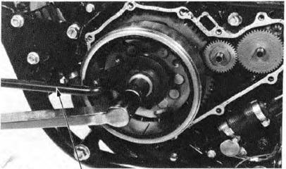


 (0.8-1.2 kg·m, 6-9 ft-lb)
 i{;)a:o:m
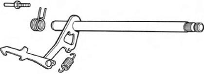

 GEA RS HIF T LINK AGE