|
Архитектура Аудит Военная наука Иностранные языки Медицина Металлургия Метрология Образование Политология Производство Психология Стандартизация Технологии |
|
|
Архитектура Аудит Военная наука Иностранные языки Медицина Металлургия Метрология Образование Политология Производство Психология Стандартизация Технологии |
CYLINDER HEAD DISASSEMBLY
Remove the valve spring cotters, retainers, springs and valves wi th the Valve Spring Compressor.
CAUTION (11 GASK ET
(2) DOWE L PINS
-.: 11 (1) VALVE SPRING COMPRESSOR 07757-0010000 OR 07957-3290001
Remove the valve stem seals and valve spring seats.
(1) VALVE STEM SEALS
(21 VALVE SPRI NG SEATS
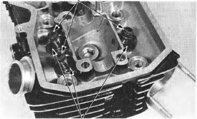
Remove carbon deposits from the combustion chamber and clean off the head gasket surf aces.
CYLIN D E R H EAD Check the spark plug hole and valve areas for cracks.
Check the cylinder head for warpage with a strai!llt edge and feeler gauge as indicated.
SERVICE LIM IT: 0.10 mm (0.004 in)
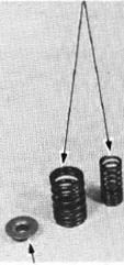
Measu re the free length of the inner and outer valve springs.
SERVICE LIMITS: I N NE R U NI: 35.58 mm (1.4008 in ) ( EX ): 43.32 mm (1.666 in) OUTER U N J: 44.3 mm (1.744 in ) ( EX): 44.29 mm (1.744 in)
R eplace th e springs i i they are shorter than the service limits.
VA LVE STEM-TO-GUIDE CLEAR ANCE
Check valve movement in the guide and measure and record each va lve stem O.D.
SERVICE LIMITS: IN: 5.45 mm (0.215 in) EX: 6.55 mm (0.258 in) NOTE
Measure and record each valve guide 1.0. SERVICE LIMIT : IN: 5.56 mm (0.219 in) EX: 6.65 mm (0.262 in) Subtract each valve nem 0.0. from the correspond· ing guide 1.0. to obtain the stem to guide clearance.
SER VICE LIMITS : IN: 0.10 mm (0.004 in) EX : 0.11 mm (0.004 in)
If the stem·to guide clearance exceeds the service limits, determine if a new guide with Handard dimensions (page 10·1) wou ld bring the clearance within tolerance. If so, replace any guides as neces sary and ream to fit.
If the stem·to-guide clearance exceeds the service limits with new guides. also replace the valves.
NOTE
VALVE GUIDE R EPLACEME N T Heat the cylinder head to 100°C (212°F) w ith a hot plate or oven.
CAUTION
(1) VALVE GUIDE REAMER 5.5 mm, 07984-2000000 (IN) 6.5 mm, 07984-6570100 (EX)
(1)
Support the cylinder head and drive out the old guides from the combust ion chamber side of the cylinder head. NOTE
Drive new guides in from the rocker arm side of the cylinder head.
VA LVE GUIDE PROJECTION A BOVE CYLINDER HEAD: IN: 19.5 ± 0.1 mm (0.768 :t 0.004 in) EX: 18.0 :t 0.1mm (0.719 :t 0.004 in)
Use cutting oil on the reamer during this operation. It is important that the reamer always be rotated in the cutting dlirection when it is inserted or removed.
Clean the head thoroughly after reaming the valve guides.
(2) VALVE GUIDE DRIVER ATTACHMENT
(1) VALVE GUIDE REAMER IN: 07984-2000000
CYLINDER HEADNALVE H O NDA VTSO OC
Clean all intake and exh aust valves thoroughly to remove carbon deposits.
Apply a ligh t coating of Prussian Blue to each valve seat. Lap each valve and seat using a rubber hose or other hand-lapping tool.
Remove and inspect each valve.
CAUTION
STANDARD: 0.9-1.1 mm (0.0354-0.0433 in) SER VICE LIMIT: 1.50 mm 10.0591 in)
If the seat is too wide, too narrow or has low spots, the seat must be ground.
Honda Valve Seat Cutters, grinder or equivalent valve seat refacing equipmen t are recommended to correct a worn va l ve seat . NOTE
Follow the refacer manufactu rer's opera ting instruct ions.
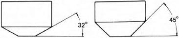
VALVE SEAT R E FACING Use a 45 degree cutter to remove any roughness or irregula ri ties from the seat.
NOTE
R eface the seat with a 45 degree cutter when a valve guide is replaced.
Use a 32 degree cutter to remove the top 1/4 of the existing valve seat material.
c:iiJ\ H O NDA
CYLINDER H E AD N ALV E H O NDA VTSO OC
NOTE
If the contact area is too h igh on the valve, the seat must be lowered usi ng a 32 degree flat cutter.
After cutting the seat. apply lapping compou nd to the valve face, and lap th e valve using l igh t pressu re. After lapping, wash all residual compound of f the cylinder head and valve.
NOTE
CYLINDE R H EADNALV E
CYLINDER HEAD ASSEMBLY I nstall the valve spring seal and a new stem seal . Lubricate each valve stem with molybdenum disul· fide grease and insert the valve into the valve guide. To avoid dama!ll! to the stem seal, tu rn the valve slowly when inserting.
I nstall the valve springs andl retai ners. The springs tigh tly wound coils should face in toward the com bustion chamber.
(1) VALVE SPR INGS ,,,,,... (3) COTTERS (41 RETAINER Q\ H O NDA.
(2) IN. V ALVE SPRINGS
NOTE
Springs wi th green pa in t are exhaust val ve springs.
I nstall the valve cotters.
CAUTION I 1 · I
(3) EX. VALVE SPRING
(1) 07757-0010000
Tap the valve stems gently with a sof t hammer to firm ly seat the cotters.
Support the cyl inder head above the work bench surface to prevent possible valve da mage.
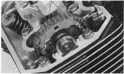
Make sure that the cam chain guide bosses are in the grooves of the cylinder.
Clean the cylinder head surface of any gasket ma terial.
(2) GROOVES
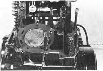
I nstall the dowel pins and a new h ead gasket. (1) HEAD GASKET
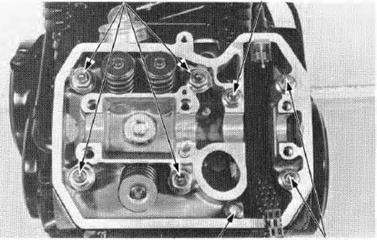
Install the cylinder head. Install and tighten the 10 and 8 mm flange nuts and cylinder bolt to the specified torQue.
TORQUE: 10 mm nut: 35-45 N·m (3.5-4.5 kg.m, 25-33 ft-lb) 8 mm nut: 20-25 N·m (2.0-2.5 kg.m, 14-18 ft lb) 8 mm bolt: 20-25 N·m (2.0-2.5 kg·m, 14-18 ft-lb) 6 mm bolt: 8-12 N·m (0.8-1.2 kg-m,6-9 ft-lb)
Install the oil pipe and tighten the bolts.
TORQUE: 7 mm bolt: 8-12 N·m (0.8-1.2 kg·m, 6-9 ft-lb) 10 mm bolt: 20-25 N·m (2.0-2.5 kg-m, 4-18 ft-lb)
Tigh:en the cam chain tensioner bolts. Install the carburetor intake pipes.
CAMSHAFT INSTALLATION Lubricate the camshaft journal surface of the cv· linder head with molybdenum disulf ide grease.
Run the camshaft through the cam chain and install the cam sprocket on the shaft f lange. (1) 10 mm NUT (2) 8 mm NUT
(3) 6 mm CYLINDER BOLT (4) 8 mm BOLT
(2)
Camshaft with tachometer gea r-F.cyl inder Camshaft whhou t tachometer gear -R .cylinder
Put each camshaft on the cylinder head with its lobe facing down. Install the front cylinder camshaft f irst as shown below.
While li fting the cam chain. rotate the crankshaf t clockwise and align the timing mark on the rotor with the index mark on the right crankcase. Front cylinder ..• ....·"F.T" Rear cylinder .....•.- - "R.T''
Al ign the ti ming marks oo the cam sprocket with the top of the cylinder head and place the cam chain on the sprocket.
Position the cam sprocket on the camshaft f lange.
NOTE
CAUTION
Apply a locking agent to the th reads and underside of the head of the cam sProcket bol t. I nstall the bolt, but do not tighten at this time.
Turn the crankshaft clockwise one tu m (360°). Apply a locking agent to the other cam sprocket bolt and install i t. Tighten the bolt to the specified torque.
TORQUE : 20-25 N·m (2.0-2.5 kg-m. 14-18 ft·lb)
Tu rn the crankshaft clockwise one more tu rn and torque the remaining bolt to the same value.
Remove the 2 mm pin holding camshaft tensioner wedge A. (1) TIMING MARK
(1)
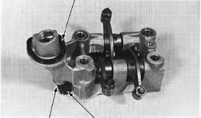
I nstall the rocker arms, rocker arm shafts and w;r.;e washers.
NOTE
Align the cut·out i n the rocker arm shaf t with the bolt hole.
(2) ROCKER ARM SHAFTS
On the front camshaft holder; install the tachometer gear,washer and seal.
I nstall the dowel pins. Pour clea n engine oil i nto the oil pockets in the head so that the cam lobes are submerged.
NOTE
(1) OIL SEAL
(1) WASHER (2) TACHOMETER GEAR
(1) DOWEL PINS CYLINDER H EADNALVE
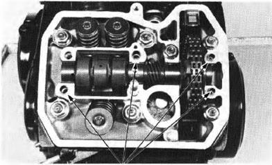
I nstall and tigh ten me camshaft holders to the specif ied torque.
TORQUE : 6 mm bol t/nut: 20-25·N·m (2.0-2.5 kg·m , 14-18 f t-lb) 6 mm SH bolt: 8-12 N·m (0.8-1.2 kg-m, 6-9 ft-lb)
|
Последнее изменение этой страницы: 2019-06-10; Просмотров: 218; Нарушение авторского права страницы

 NOTE
NOTE

 N OTE
N OTE 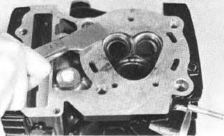
 INSPE CTI ON
 INSP ECTI ON
 VALVE SPR I N GS
 Inspect each valve for trueness,burning,scratches or abnormal nem wear.

 Do n ot us e a rorch 1 0 he ar t h e cylinder head; ir may c au se "Vlfpf11g .
 J
J VA LVE GUIDE REMOVER 5.5 mm, 07742-0010100 (IN) 6.6 mm, 07742-0010200 (EX)

 I Avo i d damag i ng the cy l i nder head.
  Ream the new valve guides after installation. NOTE
 (1) VALVE GUIDE DRIVER
 IN:07742-0010100 EX: 07742-0010
 IN: 07943-MF50100 EX: 07943-MF50200
 EX: 07984-6570100

 V ALVE SEAT INSPECTION / REFACING
 Inspect the width of each valve seat.
 VALVE SEAT CUTTERS
 CYLINDER HEAD/VALVE
 Use a 60 degree cutter to remove the bottom 1/4 of the old seat. Remove the cutter and inspect the area you have refaced.
 Use a 45 degree f inish cutter and cut the seat to the proper width. Make sure that all pitting and irregu· larities are removed . R efinish if necessary.
 VTSOOC


 Apply a thin coating of Prussian Blue to the valve seat. Press the valve th rough the valve guide and onto the seat to make a clear pattern.
 The location of the valve seat in relation to the valve face is very important for good seal i ng.
 If the con tact area is too low on the valve, the seat must be raised usi ng a 60 degree inner cutter.
 Refinish the seat to specifications, using a 45 degree f inish cutter.
 VT500 C


 THIS END TOWARDS \ COMBUSTION CHAMBER
 VALVE SPRING COMPRESSOR
 NOTE
NOTE CYLI NDER HEAD INSTALLATIO N
 •
•

 WASHERS (3) 10 mm BOLT

 Place the camshaft into its correct positions.

 CAM SPROCKET BOLT
 CAMSHAFT HOLDER INSTALLATION

 Make sure that the cam lobes are submerged i n oil.