|
Архитектура Аудит Военная наука Иностранные языки Медицина Металлургия Метрология Образование Политология Производство Психология Стандартизация Технологии |
|
|
Архитектура Аудит Военная наука Иностранные языки Медицина Металлургия Метрология Образование Политология Производство Психология Стандартизация Технологии |
Read these word combinations and remember their translation. ФЕДЕРАЛЬНОЕ ГОСУДАРСТВЕННОЕ БЮДЖЕТНОЕ ОБРАЗОВАТЕЛЬНОЕ УЧРЕЖДЕНИЕ ВЫСШЕГО. «КЕРЧЕНСКИЙ ГОСУДАРСТВЕННЫЙ МОРСКОЙ ТЕХНОЛОГИЧЕСКИЙ УНИВЕРСИТЕТ»Стр 1 из 17Следующая ⇒
ФЕДЕРАЛЬНОЕ ГОСУДАРСТВЕННОЕ БЮДЖЕТНОЕ ОБРАЗОВАТЕЛЬНОЕ УЧРЕЖДЕНИЕ ВЫСШЕГО ОБРАЗОВАНИЯ «КЕРЧЕНСКИЙ ГОСУДАРСТВЕННЫЙ МОРСКОЙ ТЕХНОЛОГИЧЕСКИЙ УНИВЕРСИТЕТ»
Кафедра иностранных языков
Маркевич Т.А. АНГЛИЙСКИЙ ЯЗЫК
Методические указания к практическим занятиям и самостоятельной работе для студентов (курсантов) 3 курса специальности 26.05.06 «Эксплуатация судовых энергетических установок» очной и заочной формы обучения
Керчь, 2016 г.
СОДЕРЖАНИЕ
ВВЕДЕНИЕ
Данные Методические указания представляют сборник текстов и упражнений, предназначенных для аудиторной и самостоятельной работы студентов специальности 26.05.06 «Эксплуатация судовых энергетических установок» и охватывает круг вопросов, связанных с особенностями конструкций паровых турбин, их эксплуатации и областями применения. Цель сборника – развитие навыков технического перевода, анализа оригинальной литературы по специальности, накопление и усвоение лексического материала, необходимого как для чтения, так и развития навыков устной речи. Упражнения направлены на формирование словарного запаса, преодоление трудностей перевода и приобретение разговорных навыков. Сборник рассчитан на студентов, имеющих запас знаний и продолжающих изучение английского языка в ВУЗе. Тематика текстов подобрана в соответствии с требованиями к обязательному минимуму содержания дисциплины «Английский язык», входящей в основную образовательную программу подготовки специалистов по специальности 26.05.06 «Эксплуатация судовых энергетических установок» государственного образовательного стандарта высшего образования и согласована со специалистами кафедры СЭУ. Пособие рассчитано на 42 учебных часа и предназначена для изучения в 6 семестре.
UNIT 1 STEAMTURBINE A turbine is a rotary engine that extracts energy from a fluid flow and converts it into useful work. The simplest turbines have one moving part, a rotor assembly, which is a shaft or drum with blades attached. Moving fluid acts on the blades, or the blades react to the flow, so that they move and impart rotational energy to the rotor. To understand the functioning of a steam turbine, one must first be familiar with some of the terminology associated with it. The rotor is the spinning component that has wheels and blades attached to it. The blade is the component that extracts energy from the steam.
Figure 1.1 Energy conversion in a steam turbine
The steam turbine is a device for obtaining mechanical work from the energy stored in steam. A steam turbine is a device that extracts thermal energy from pressurized steam and uses it to do mechanical work on a rotating output shaft. Its modern manifestation was invented by Sir Charles Parsons in 1884. In 1878, a Swedish engineer, Carl G. P. de Laval developed a simple impulse turbine, using a convergent-divergent (supersonic) nozzle, which ran the turbine to a maximum speed of 100, 000 rpm. In 1897 he constructed a velocity-compounded impulse turbine (a two-row axial turbine with a row of guide vane stators between them). AugusteRateau in France started experiments with a de Laval turbine in 1894, and developed the pressure compounded impulse turbine in the year 1900. In the USA, Charles G. Curtis patented the velocity compounded de Laval turbine in 1896 and transferred his rights to General Electric in 1901. Steam enters the turbine with a high energy content and leaves after giving up most of it. The high-pressure steam from the boiler is expanded in nozzles to create a high-velocity jet of steam. The nozzle acts to convert heat energy in the steam into kinetic energy. This jet is directed into blades mounted on the periphery of a wheel or disc. The steam does not 'blow the wheel around'. The shaping of the blades causes a change in direction and hence velocity of the steam jet. Now a change in velocity for a given mass flow of steam will produce a force which acts to turn the turbine wheel, i.e. mass flow of steam (kg/s) x change in velocity (m/s) = force (kg m/s2). This is the operating principle of all steam turbines, although the arrangements may vary considerably. The steam from the first set of blades then passes to another set of nozzles and then blades and so on along the rotor shaft until it is finally exhausted. Each set comprising nozzle and blades is called a stage. Steam turbine has higher thermal efficiency than reciprocating steam engines. The brake horsepower of steam turbines can range from a few HP to several hundred thousand HP in single units. Hence they are quite suitable for large thermal power stations. Unlike reciprocating engines, the turbines do not need any flywheel, as the power delivered by the turbine is uniform. Steam turbines are perfectly balanced and hence present minimum vibrational problem. High rpm l8000 - 24000 can be developed in steam turbines but such a high speed generation is not possible in the case of reciprocating steam engines. Some amount of input energy of steam is lost as the reciprocating motion of the piston is converted to circular motion. Unlike reciprocating steam engines, no internal lubrication is required for steam turbines due to the absence of rubbing parts. Steam turbines, if well designed and properly maintained, are more reliable and durable prime movers than steam engines. Advantages of turbines 1) Large power achieved by relatively small size 2) High efficiency 3) Simple design 4) High revolution Disadvantages of steam turbines 1) High efficiency is ordinarily obtained only at high speed 3) These devices are heavy and cumbersome. 4) Turbines can rotate in only one direction. VOCABULARY usefulwork - полезнаяработа toconvert - превращать to expand - расширяться to extract - извлекать increaseinvelocity - увеличение скорости пара shaft - вал blade, vane - лопатка · movingblades - рабочие лопатки · fixedblades – неподвижные (направляющие) лопатки · stationaryblades -неподвижные (направляющие) лопатки heatengine - тепловой двигатель torevolve - вращаться stationarynozzle - неподвижное сопло turbinewheel – диск турбины steamjet - паровая струя toderivefrom - произвести от rotation - вращение shippropulsion - движение судна drive - привод thearrangements - механизмы stage – ступень, каскад thermalefficiency – тепловой кпд reciprocatingsteamengines -поршневыепаровыедвигатели brakehorsepower- лошадинаясила flywheel -маховик uniform - равномерный balancing - балансировка inputenergyofsteam – энергияпаранавходе circularmotion - круговое движение dueto - из-за theabsence - отсутствие rubbingparts - трущиеся детали primemover - двигатель
EXERCISES UNIT 2 TURBINE TYPES Impulse An impulse turbine is a type of steam turbine where the rotor derives its rotational force from the impact force, or the direct push of steam on the blades. The impulse turbine was first built in 1883 by the Swedish engineer De Laval. The impulse turbine consists of a rotor mounted on a shaft that is free to rotate. Attached to the rotor are a set of curved blades. Nozzles then direct the high pressure and high temperature steam towards the blades of the turbines. The blades catch the impact force of the rapidly moving steam and rotate from this force. In the impulse turbine the steam is expanded within the nozzle and there is no any change in the steam pressure as it passes over the blades. IMPULSE TURBINE PRINCIPLE
Figure 2.1 Impulse turbine Principle
The above diagram of impulse turbine blades shows: 1) The steam first enters the impulse turbine through a fixed nozzle. 2) The steam strikes the blades that are free to rotate with a strong enough force to move the blades. 3) The steam exits the blades towards the condensing system of the steam turbine generator system. 4) The direction of the blades due to the force of steam. This next diagram shows the rotational force of the impulse turbine: From the above diagram of the impulse turbine we see: 1) The steam enters from a fixed nozzle. 2) The steam strikes the rotating blade with enough force to spin the impulse turbine.
Figure 2.2Rotational force of the impulse turbine
Reaction turbines Reaction turbines are invited by C.A Parsons. A reaction turbine is a type of steam turbine that works on the principle that the rotor spins, as the name suggests, from a reaction force rather than an impact or impulse force. In this type of turbine, there is a gradual pressure drop and takes place continuously over the fixed and moving blades. The rotation of the shaft and drum, which carrying the blades is the result of both impulse and reactive force in the steam. The reaction turbine consists of a row of stationary blades and the following row of moving blades. The fixed blades act as a nozzle which are attached inside the cylinder and the moving blades are fixed with the rotor as shown in figure. When the steam expands over the blades there is gradual increase in volume and decrease in pressure. But the velocity decreases in the moving blades and increases in fixed blades with change of direction. Because of the pressure drops in each stage, the number of stages required in a reaction turbine is much greater than in an impulse turbine of same capacity. It also concluded that as the volume of steam increases at lower pressures therefore the diameter of the turbine must increase after each group of blade rings. The more correct term for this blade arrangement is 'impulse-reaction'. REACTION TURBINE PRINCIPLE Notice from the diagram of the reaction turbine above that: 1) The steam enters through a section of curved blades in a fixed position. 2) The steam then enters the set of moving blades and creates enough reactive force to rotate them, 3) The steam exits the section of rotating blades. 4) The direction of rotation.
Figure 2.3 Reaction turbine principle
There are three main forces that act to move a reaction turbine. First, from the reactive force that is created on the moving blades as it expands and increases in velocity as it moves through the nozzle shaped spaces between the blades. Second, from the reactive force produced on the moving blades as the steam passes through and changes directions. Third, and to a lesser extent, from the impact force of the steam on the blades helps rotate the reaction turbine.
VOCABULARY
1. turbine - турбина · action (impulse)-активнаятурбина · aft (astern) (back-up) -турбиназаднегохода · ahead -турбинапереднего хода · axial(-flow) –осеваятурбина · back-pressure – турбина с противодавлением · bucketwheel –турбина с тангенциальным потоком рабочего тела · combined –комбинированнаятурбина · compound –двухкорпусная турбина · cross-compound – двухвальная (турбина) · doublereductiongear – турбоагрегат с двухступенчатым редуктором · double-stage(d) – двухступенчатаятурбина · dual-flow – двухпоточнаятурбина · geared – турбина с зубчатой (редукторной) передачей · low-pressure –турбина низкого давления · multistage(d) – многоступенчатая турбина · output – силовая турбина · pressure (reaction) - реактивнаятурбина · radialflow - радиально-проточная турбина · single-cylinder –однокорпуснаятурбина · tandem-compound–одновальная (турбина) · twin-shaft – двухвальная турбина 2. gland - уплотнение 3. bearing - подшипник 4. gearedunit - турбозубчатый агрегат 5. turbo-electricinstallation - турбоэлектрическая установка 6. nozzle ring -аппаратсопловой 7. dynamic balancing - балансировкадинамическая 8. intake duct - воздухозаборник 9. diaphragm - диафрагма 10. unbalance - дисбаланс 11. diffuser - диффузор 12. combustion chamber – камерасгорания 13. throttle valve - клапандроссельный 14. casing, housing - корпус 15. stage, step -stage, step 16. maneuveringgear - устройство маневренное 17. bladeroot - хвост лопатки 18. velocity of steam entering - скоростьвходящегопара 19. velocity of steam leaving - скоростьвыходящегопара 20. clearance - зазор 21. exhaust – выход 22. airfoilblade — лопатка аэродинамического профиля 23. bladeairfoil — аэродинамический профиль лопатки; перо лопатки 24. profileblade — профилированная лопатка; фасонная лопатка 25. bladeprofile — профиль поперечного сечения лопатки EXERCISES 1. Read these word combinations and remember their translation. The turbine wheel; rotational force; impact force; the direct push of steam on the blades; rotor mounted on a shaft; set of curved blades; rapidly moving steam; within the nozzle; no any change in the steam pressure; fixed nozzle; a strong enough force; the condensing system; the steam turbine generator system; the rotor spins; reaction force; an impact or impulse force; gradual pressure drop; gradual increase in volume; takes place continuously; the fixed and moving blades; the result of both impulse and reactive force in the steam; a row of stationary blades; the number of stages required; turbine of same capacity; blades of profile and airfoil types.
2. Give English equivalents to the following.
Активная турбина, реактивная турбина, одноступенчатая турбина, многоступенчатая турбина, преобразовывать в механическую энергию, форма лопаток, действующая на лопатки сила, сопловое колесо, активные лопатки, вал турбины, осевое усилие, расширение пара, симметричная форма лопаток, лопаточный канал почти постоянного сечения, подаваться под определенным углом, расширяющиеся каналы, криволинейные суживающиеся каналы, кпд турбины, относительная скорость пара, высокая частота вращения, значительные перепады тепла
Reaction Turbine · Reaction turbines are invited … C.A Parsons. It has three stages, each composed of a row of fixed blades and row of moving blades. · The stationary blades are designed … such a fashion that the passages between them form the flow areas of nozzles, so they become nozzles … full steam admission … the rotor periphery. · The moving blades of a reaction turbine are differ … the impulse turbine blades … that they are not symmetrical and act partly as nozzles. · The pressure drops … all rows of blades. The pressure change gets greater … the steam pressure gets higher. · The absolute steam velocity changes … each stage and repeats from stage to stage. The Impulse Turbine · It is also called the de Laval turbine … its inventor. In this type a single rotor is used … which impulse blades are attached. · The steam is fed … one or several nozzles which do not extended completely around the circumference of the rotor, so only part of the blades are impinged … any one time. · The pressure drop in this type occurs mainly in the nozzle and the velocity drops … the blades. · The clearance...the rotating and stationary surfaces is greater than in the reaction type steam turbine. Complete the table.
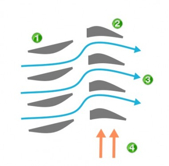
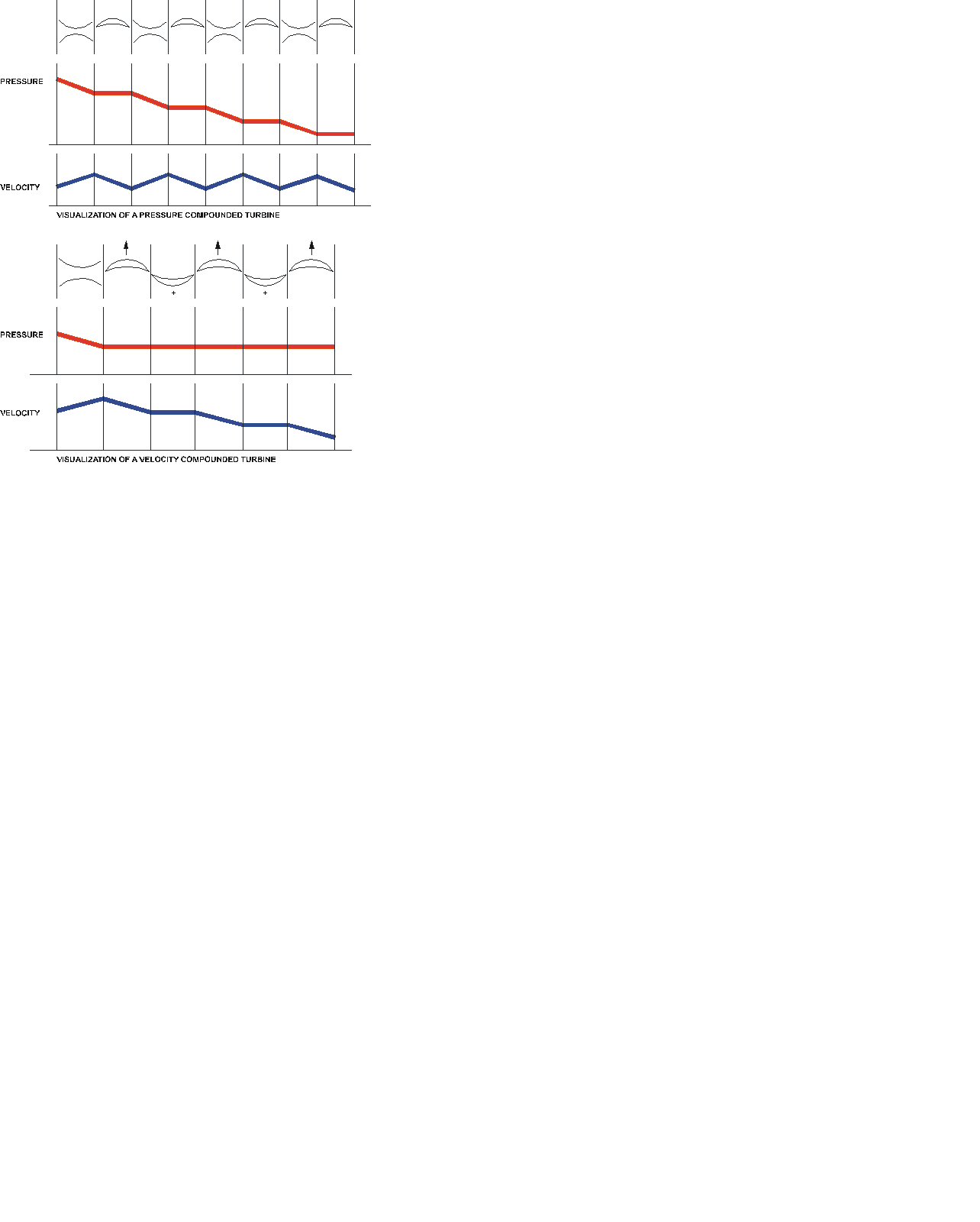
UNIT 3 Velocity Compounding: There are number of moving blades separated by rings of fixed blades as shown in the figure. All the moving blades are keyed on a common shaft. When the steam passed through the nozzles where it is expanded to condenser pressure, its velocity becomes very high. This high velocity steam then passes through a series of moving and fixed blades. When the steam passes over the moving blades, its velocity decreases. The function of the fixed blades is to re-direct the steam flow without altering its velocity to the following next row moving blades where a work is done on them and steam leaves the turbine with allow velocity as shown in diagram. VELOCITY COMPOUNDED TURBINE
Figure 3.1Visualization of a Velocity Compounded Turbine It is called Curtis stage turbine. •It is composed of three zones of blades, where the first and third zones are moving, while the middle blade stage is stationary. •This configuration results in velocity reduction. •Any number of rows can be used as figure. Such staging usually is built with successively increasing blade angles and flatter and thinner blades toward the last row.
Pressure Compounding: Pressure compounding of an impulse turbine is the use of a number of stages of nozzle and blade to reduce progressively the steam pressure. This results in lower or more acceptable steam flow speeds and a better turbine efficiency. These are the rings of moving blades which are keyed on a same shaft in series, are separated by the rings of fixed nozzles. The steam at boiler pressure enters the first set of nozzles and expanded partially. The kinetic energy of the steam thus obtained is absorbed by moving blades. The steam is then expanded partially in second set of nozzles where its pressure again falls and the velocity increase the kinetic energy so obtained is absorbed by second ring of moving blades. This process repeats again and again and at last, steam leaves the turbine at low velocity and pressure. During entire process, the pressure decreases continuously but the velocity fluctuates as shown in diagram. PRESSURE COMPOUNDED TURBINE
Figure 3.2Visualization of a Velocity Compounded Turbine
It is calledRateau turbine The idea of this turbine to overcome the high velocity in the single stage and the pressure drop in the nozzle is by dividing up the total enthalpy equally among many single-stage impulse turbines in series. Thus the inlet steam velocities to each stage are equal and due to a reduced h The pressure compounded impulse turbine has the advantages of reduced blade velocity, reduced steam velocity (friction) and equal work among the stages. The disadvantages are the pressure drop across the fixed rows of nozzles, which requires leak-tight diaphragms and large number of stages. Pressure compounded turbines are ordinarily used for large turbines where efficiency is more important than capital cost.
EXERCISES 1. Read these word combinations and remember their translation. The compounding, reducing the wheel or rotor speed, optimum value, the process of arranging the expansion of steam, the utilization of kinetic energy, a multiple system of rotors in series, keyed on a common shaft, separated by rings of fixed blades, without altering the velocity, successively increasing blade angles, to reduce progressively, turbine efficiency, lower or more acceptable steam flow speeds, to expand partially, during entire process, the velocity fluctuates, dividing up the total enthalpy, leak-tight diaphragms, capital cost, astern blading, friction losses, row of moving blades, the condenser pressure, to re-direct the steam flow.
UNIT 4 VOCABULARY 1. turbinewheel – диск турбины 2. turbine - турбина · action (impulse)-активная турбина · aft (astern) (back-up) -турбиназаднегохода · ahead -турбинапереднего хода · axial(-flow) –осеваятурбина · back-pressure – турбина с противодавлением · bucketwheel –турбина с тангенциальным потоком рабочего тела · combined –комбинированнаятурбина · compound –двухкорпусная турбина · cross-compound – двухвальная (турбина) · doublereductiongear – турбоагрегат с двухступенчатым редуктором · double-stage(d) – двухступенчатаятурбина · dual-flow – двухпоточнаятурбина · geared – турбина с зубчатой (редукторной) передачей · low-pressure –турбина низкого давления · multistage(d) – многоступенчатая турбина · output – силовая турбина · pressure (reaction) - реактивнаятурбина · radialflow - радиально-проточная турбина · single-cylinder –однокорпуснаятурбина · tandem-compound–одновальная (турбина) · twin-shaft – двухвальная турбина 3. blade, vane - лопатка · movingblades - рабочие лопатки · fixedblades – неподвижные (направляющие) лопатки · stationaryblades -неподвижные (направляющие) лопатки 4. heatengine - тепловой двигатель 5. torevolve - вращаться 6. stationarynozzle - неподвижное сопло 7. gland - уплотнение 8. bearing - подшипник 9. usefulwork - полезная работа 10. toconvert - превращать 11. steamjet - паровая струя 12. toderivefrom - произвести от 13. rotation - вращение 14. shippropulsion - движение судна 15. drive - привод 16. increaseinvelocity - увеличение скорости пара 17. gearedunit - турбозубчатый агрегат 18. turbo-electricinstallation - турбоэлектрическая установка 19. nozzle ring -аппаратсопловой 20. dynamic balancing - балансировкадинамическая 21. intake duct - воздухозаборник 22. diaphragm - диафрагма 23. unbalance - дисбаланс 24. diffuser - диффузор 25. combustion chamber – камерасгорания 26. throttle valve - клапандроссельный 27. casing, housing - корпус 28. stage, step -stage, step 29. maneuveringgear - устройство маневренное 30. bladeroot - хвост лопатки 31. velocity of steam entering - скоростьвходящегопара 32. velocity of steam leaving - скоростьвыходящегопара 33. clearance - зазор 34. exhaust - выход EXERCISES 1. Find in the text English equivalents for the following: · активная/реактивная турбина · одновальная/двухвальная/многовальная турбина, · многокорпусная/ двухкорпусная /однокорпусная турбина · однопоточная/двухпоточная турбина · многоступенчатая /одноступенчатая турбина · турбина со ступенями давления/со ступенями скорости/комбинированная (со ступенями скорости и давления) · паровая/газовая турбина · осевая/радиальная/тангенциальная турбина · турбина высокого/ среднего/низкого давления · турбина двойного давления · турбина переднего/ заднего хода · турбина с противодавлением /конденсационная /теплофикационная · предвключенная /приключенная турбина · турбина осевая/ радиальная/ радиально-осевая · одноцилиндровая/двухцилиндровая/многоцилиндровая турбина
UNIT 5 EXERCISES
UNIT 6 BLADES The energy conversion takes place through the turbine blades. The interior of a turbine comprises several sets of blades, or buckets as they are more commonly referred to. One set of stationary blades is connected to the casing and one set of rotating blades is connected to the shaft. This blades convert the chemical or thermal energy of working fluid into kinetic energy and then from kinetic energy to mechanical energy as rotation of the shaft. There are two types of blade, fixed and moving blade. Moving blade is also of two types. One is impulse blade and another reaction blade. Blade design is extremely important in attaining high turbine reliability and efficiency. A large selection of efficient blade profiles have been developed and proven by extensive field service allowing for optimal blade selection for all conditions of service. Blades are milled from stainless steel within strict specifications for proper strength, damping and corrosion resistant properties. Disk profiles are designed to minimize centrifugal stresses, thermal gradient and blade loading at the disk rims. The term buckets and blades are often used synonymously. Although the shape and appearance are similar, it has usually been considered that buckets are used in the impulse type turbine and blades, both stationary and rotating, are used in the reaction type steam turbine. Buckets of impulse turbines and blades of some reaction turbines have a shroud band, either continuous or in sections, either welded, brazed or riveted to the blade tip, which acts as a bracing to the blades and maintains radial clearance with the turbine casing. The blades are fitted into grooves of various designs cut into the wheels.
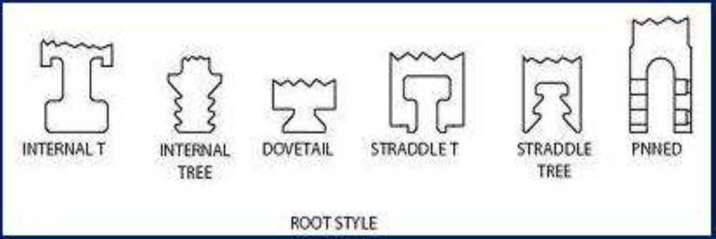
Figure 6.1 Root Style
When the turbine rotor is rotating at high speed the blades will be subjected to considerable centrifugal force and variations in steam velocity across the blades will result in blade vibration. Expansion and contraction will also occur during turbine operation; therefore a means of firmly securing the blades to the wheel is essential. A number of different designs have been employed (Figure). Fitting the blades involves placing the blade root into the wheel through a gate or entrance slot and sliding it into position. Successive blades are fitted in turn and the gate finally closed with a packing piece which is pinned into place. Shrouding is then fitted over tenons on the upper edge of the blades. Alternatively, lacing wires may be passed through and brazed to all the blades. Various root fixing shapes have been developed for turbine blading to suit both construction requirements and conditions under which turbines operate. The most popular types of blade root fixing available are: ¨ Grooves ¨ Straddle ¨ Rivet Groove construction The groove type of root fixing fits into a machined grove around the circumference of the rotor wheel or disc. Blade roots are installed through the closing blade window and then slid around the circumference of the disc into their desired position. The last blade root is installed in the closing blade opening and secured in position by dowel(s). Straddle construction Straddle construction is where the blade root fits over the machining on the outer periphery of the rotor wheel or disc. Once again with this type of construction the blade roots are installed through the closing blade window slid around the circumference of the disc into position, then the last blade inserted is doweled in the closing blade window location. Rivet construction Rivet construction is where the blade root either inserts into a groove or straddles the disc and all blades are doweled into position. Peripheral blade fixing On larger blading where the blade length is relatively long a system of lacing wire or shroud rings are installed to give the blading additional support and reduce vibration. The lacing wire is installed a small distance from the outer ends of the blades while the shroud rings are fitted to tangs on the outer edges of the blades and secured by peening the tangs. DIAPHRAGMS
A fixed blade assembly is very important for turbine blading. It is also known as diaphragm. Only impulse turbines have diaphragms. Partitions between pressure stages in a turbine's casing are called diaphragms. Diaphragms are circular plates made up of two semi-circular halves. A central semi-circular hole in each is provided for the shaft to pass through. One-half of the diaphragm is fitted into the top of the casing, the other half into the bottom. They hold the vane-shaped nozzles and seals between the stages. The nozzles are housed in the diaphragm around its periphery. The central hole in the diaphragm is arranged with projections to produce a labyrinth gland around the shaft. Usually labyrinth-type seals are used. Nozzle rings and diaphragms are specifically designed and fabricated to handle the pressure, temperature and volume of the steam, the size of the turbine and the required pressure drop across the stage. The nozzles used in the first stage nozzle ring are cut from stainless steel. Steam passages are then precision milled into these nozzle blocks before they are welded together to form the nozzle ring. NOZZLES Nozzles serve to convert the high pressure and high energy of the steam into a high-velocity jet of steam with a reduced pressure and energycontent. The steam inlet nozzles are arranged in several groups with all but the main group having control valves. In this way the power produced by the turbine can be varied, depending upon how many nozzle control valves are opened. Both impulse and reaction turbines have steam inlet nozzles. The nozzles in the intermediate pressure stages are formed from profiled stainless steel nozzle sections and inner and outer bands. These are then welded to a circular center section and to an outer ring then precision machined. The low-pressure diaphragms in condensing turbines are made by casting the stainless nozzle sections directly into high-strength cast iron. This design includes a moisture catching provision around the circumference which collects released moisture and removes it from the steam passage. Additional features such as windage shields and inter-stage drains are used as required by stage conditions to minimize erosion. All diaphragms are horizontally split for easy removal and alignment adjustment.
EXERCISES
UNIT 7 CASINGS AND SEALS CASING The turbine casing completely surrounds the rotor and provides the inlet and exhaust passages for the steam. The casings of turbine cylinders are of simple construction to minimize any distortion due to temperature changes. Casings are usually split horizontally to permit easier access for inspection and repair. The flanges are accurately machined to ensure a steam-tight metal-to-metal fit, and the flanges are strongly bolted together. Flange seals, except for corrective maintenance measures, are not normally used. In some (high temperature) units, both top and bottom casing halves are made of two vertical casings bolted together and seal-welded. The inlet end is made of alloy steel (Cr-Ni), while the exhaust end is made of carbon steel. The flanges in the casing are bolted together. One method of joining the top and bottom halves of the cylinder casing is by using flanges with machined holes. Bolts or studs are insertion into these machined holes to hold the top and bottom halves together. To prevent leakage from the joint between the top flange and the bottom flange the joint faces are accurately machined. Another method of joining the top and bottom cylinder flanges is by clamps bolted radially around the outer of the cylinder. The outer faces of the flanges are made wedge-shaped so that the tighter the clamps are pulled the greater the pressure on the joint faces. Each casing has a steam chest to receive the incoming steam and to deliver it to the first stage nozzles. In marine turbines the steam chest is mounted directly on the casing. The steam chest, located on the forward, upper half of the HP turbine casing, houses the throttle valve assembly. This is the area of the turbine where main steam first enters the main engine. The throttle valve assembly regulates the amount of steam entering the turbine. After passing through the throttle valve, steam enters the nozzle block. Since a reaction force acts on stationary nozzles and blading, the turbine casing must be securely fixed to a foundation to resist these forces and to prevent the turbine from moving. Access openings are sometimes provided in the casing to allow the checking of blading clearances. Other opening in the casing include drain connections, steam bypass connections, openings for rotor ends, pressure gages, thermometers, relief valves and holes for balancing the rotor. GLANDS AND GLAND SEALING Steam is prevented from leaking out of the rotor high-pressure end and air is prevented from entering the low-pressure end by the use of glands. A combination of mechanical glands and a gland sealing system is usual. Mechanical glands are usually of the labyrinth type. Figure 7.1 (a) Water-sealed glands and labyrinth seals as used on the high-pressureend of condensing turbines. (b) Labyrinth-type gland as used on noncondensing turbines. Labyrinth packing is used widely in steam turbine practice. It gets its name from the fact that it is so constructed that steam in leaking must follow a winding path and change its direction many times. This device consists of a drum that turns with the shaft and is grooved on the outside. The drum turns inside a stationary cylinder that is grooved on the inside. There are many different types of labyrinth packing, but the general principle involved is the same for all. Steam in leaking past the packing is subjected to a throttling action. This action produces a reduction in pressure with each groove that the steam passes. The amount of leakage past the packing depends on the clearance between the stationary and the rotating elements. The gland sealing system operates in conjunction with the labyrinth gland where a number of pockets are provided. The system operates in one of two ways. When the turbine is running at full speed steam will leak into the first pocket and a positive pressure will be maintained there. Any steam which further leaks along the shaft to the second pocket will be extracted by an air pump or air ejector to the gland steam condenser. Any air which leaks in from the machinery space will also pass to the gland steam condenser. At very low speeds or when starting up, steam is provided from a low-pressure supply to the inner pocket. The outer pocket operates as before. The gland steam sealing system provides the various low-pressure steam supplies and extraction arrangements for all the glands in the turbine unit. Carbon packing is composed of rings of carbon held against the shaft by means of springs. Each ring fits into a separate groove in the gland casing. Carbon packing is sometimes used to pack the diaphragms of impulse turbines. Steam seals are used in connection with carbon packing. This is essential when carbon packing is used on the low-pressure end of condensing turbines, because if there is a slight packing leak, steam instead of air will leak into the condenser. In operating a turbine equipped with carbon packing, a slight leak is desirable because a small amount of steam keeps the packing lubricated. Flexible metallic packing is used to pack small single-stage turbines operating at low backpressure. In most cases the pressure in the casing of these turbines is only slightly above atmospheric pressure. The application is the same as when this packing is used for other purposes, except that care must be exercised in adjusting. Due to the high speed at which the shaft operates, even a small amount of friction will cause overheating. A water-packed gland consists of a centrifugal-pump runner attached to the turbine shaft. The runner rotates in a chamber in the gland casing. In some designs, water is supplied to the chamber at a pressure of 3 to 8 psi and is thrown out against the sides by the runner, forming a seal. Water seals are used in connection with labyrinth packing to prevent the steam that passes the packing from leaking into the turbine room. Such a seal is also used on the low-pressure end of condensing turbines. In this case the leakage to the condenser is water instead of air. The glands are usually supplied with condensate water for sealing to prevent contamination of the condensate water. Seal designs are continuously being improved to minimize steam leakage and thus improve turbine performance. EXERCISES
UNIT 8 Single reduction gear This arrangement consists of only of one pair of gears. The reduction gear box consists of ports through which the propeller shaft and engine shaft enters the assembly. A small gear known as a pinion is driven by the incoming engine shaft. The pinion directly drives a large gear mounted on the propeller shaft. The speed is adjusted by making the ratio of the speed reduction to the diameter of pinion and gear proportional. Generally, a single gear assembly has a gear double the size of a pinion. Double reduction gear Double reduction gears are generally used in applications involving very high speeds. In this arrangement the pinion is connected to the input shaft using a flexible coupling. The pinion is connected to an intermediate gear known as the first reduction gear. The first reduction gear is then connected to a low speed pinion with the help of one more shaft. This pinion is connected to the second reduction gear mounted directly on the propeller shaft. Such arrangement facilitates the reduction of speed to a ratio as high as 20: 1. Single or double reduction systems may be used, although double reduction is more usual. With single reduction the turbine drives a pinion with a small number of teeth and this pinion drives the main wheel which is directly coupled to the propeller shaft. With double reduction the turbine drives a primary pinion which drives a primary wheel. The primary wheel drives, on the same shaft, a secondary pinion which drives the main wheel. The main wheel is directly coupled to the propeller shaft. All modern marine gearing is of the double helical type. Helical means that the teeth form part of a helix on the periphery of the pinion or gear wheel. This means that at any time several teeth are in contact and thus the spread and transfer of load is much smoother. Double helical refers to the use of two wheels or pinions on each shaft with the teeth cut in opposite directions. This is because a single set of meshing helical teeth would produce a sideways force, moving the gears out of alignment. The double set in effect balances out this sideways force. Double helical type gears are capable of transmitting large power loads smoothly, and do not impart axial thrust to either the driving member or the driven member. In most reduction gears, all pinions are completely machined out of specially heat-treated nickel-steel forgings. The gear wheels are generally of built-up construction, with the teeth cut in forged steel bands which are welded to steel webs. The first reduction gears are generally welded on their respective shafts. The bull gear is usually pressed on the shaft against a locating shaft shoulder, secured by one or more keys. Lubrication of the meshing teeth is from the turbine lubricating oil supply. Sprayers are used to project oil at the meshing points both above and below and are arranged along the length of the gear wheellocked, with a locknut, on the shaft. Coupling Since the shaft (rotor) is made in small parts due to forging limitations and other technological and economic reasons, the couplings are required between any two rotors. This coupling permits angular misalignment, transmits axial thrust and ensures axial location. The couplings are either rigid or semi flexible. The former neither permits angular nor lateral defection while the later permits only angular defection. Number of critical speeds depends upon the modes of vibrations and hence the type of coupling provided between rotors. These couplings must be capable of transmitting heavy loads and in some turbines are required to accommodate for axial expansion and contraction. The types of couplings generally employed in power plants are: · Flexible coupling · Solid shaft coupling Where axial shaft movement is required a flexible coupling is employed and these are either: 1. Sliding claw (or tooth) 2. Flexible connection (between the two flanges) Flexible couplings provide longitudinal and radial flexibility between the input shaft and the pinion. This permits each shaft to be adjusted axially and radially to its proper position without imposing excessive forces. In most installations the flexible couplings are of the gear type. Power is transmitted through a floating intermediate member with external teeth that mesh with the internal teeth of the shaft rings (sleeve) mounted on the driving and driven shafts. Turning gear All geared turbine installations are equipped with a turning gear. The turning gear on a turbine installation is a reversible electric motor driving a gearwheel which meshes into the high-pressure turbine primary pinion. The unit is used for turning the main engine during warming-up and securing periods so that the turbine rotor may heat or cool evenly. (The rotor of a hot turbine or of one that is in the process of being warmed up, with gland sealing steam cut in, will become bowed or distorted if left stationary even for a few minutes.) The turning gear is used for other routine purposes such as for turning the engine in order to bring the reduction gear teeth into view during routine inspection. In addition, the turning gear is used for the required daily jacking of the main engines.
EXERCISES
UNIT 9 TURBINE BEARINGS Although bearings in main propulsion units vary greatly in size, composition and lubrication, their purposes are the same. Bearings are used to guide and support rotating or reciprocating elements and to prevent free axial or radial movement of these elements. Radial or journal bearingsare designed to carry loads applied in a plane perpendicular to the axis of the shaft. Thrust bearingsare designed to carry loads applied in the same direction as the axis of the shaft and are used to prevent free endwise movement. Turbine bearings are steel backed, white-metal lined and supported in adjustable housings to allow alignment changes if required. Turbine journal bearings maintain the radial alignment of the turbine and supports the weight of the rotor. Bearings are spherically seated allowing for slight radial misalignment during installation only. They are located on the forward and after end of both turbine rotors. Both the bearings are of a double-tilting pad type. The bearing metal is divided into six pads which are self-aligned. A center adjustment of these bearings can easily be made with shimmed pads. Double tilting pad bearing provides maximum stability and freedom from shaft vibration. The tilting-pad design consists generally of six steel pads (shoes) with babbitt linings on the bearing surface. The pads are installed on the inner of bearing ring, and can move radial and axial direction. Therefore, the pads move smoothly, and maintain the correct alignment at all conditions. Hook fits in the inner of bearing ring retain the pads, and the pads are prevented from rotating by means of loose-fitting lock pins. Turbine thrust bearings absorb any axial thrust created in the turbine and also maintain the axial position of the rotor in the casing. The thrust bearings are double acting, segmented shoe, Kingsbury type thrust bearings. They are usually located on the forward end of each turbine rotor. The thrust bearing consists of a collar rigidly attached to the turbine shaft rotating between two babbitt-lined shoes. The clearance between the collar and the shoes is small. The piston is attached to the spindle, and steam pressure is exerted on one side and atmospheric pressure is exerted on the other side. The difference in pressure produces a force that balances the thrust exerted on the rotating blades. If the shaft starts to move in either direction, the collar comes into contact with the shoes, and the shaft is held in proper position. Larger thrust bearings have several collars on the shaft and a corresponding number of stationary shoes. The Kingsbury thrust bearing is used when a large thrust load must be carried to maintain the proper axial position in the turbine cylinder. The thrust collar is the same as that used in the common type of thrust bearing. The thrust shoes are made up of segments that are individually pivoted. With this arrangement, the pressure is distributedequally not only between the different segments but also on the individual segments. The openings between the segments permit the oil to enter the bearing surfaces. Almost 10 times as much pressure per square inch can be carried on the Kingsbury-type bearing as on the ordinary thrust bearing. Axial position of the bearing and turbine rotor may be adjusted by liners, located at the retainer rings, on each end of the bearing. The bearing is lubricated by circulating oil to all its moving parts. The impulse turbine does not require as large a thrust bearing as the reaction turbine because there is little or no pressure drop through the rotating blades. However, the thrust bearing must be used to ensure proper clearance between the stationary and rotating elements. Reaction turbines that do not have some method of balancing the force caused by the drop in pressure in the rotating blades must be equipped with large thrust bearings. Turbine bearings are subjected to very severe service and require careful attention on the part of the operator. Most turbines operate at high speed (3600 rpm) and are subjected to the heat generated in the bearing itself as well as that received from the high-temperature steam. These conditions make necessary some method of cooling. In some cases the bearings are cooled by water jacketing; in others the oil is circulated through a cooler.
VOCABULARY
axial bearing - осевойподшипник ball bearing - шарикоподшипник bearing bracket - консольнаяопораподшипника bearing cap - крышкаподшипника bearingcup - втулка подшипника; обойма подшипника bearingweardetector - индикатор степени износа подшипника bearingtab — замок вкладыша bearingbox — коробка подшипника; подшипниковый узел; букса bearingend — конец с подшипником; торец подшипника bearingkit — комплект вкладышей bearingnut — гайка подшипника bearingpad — подушка подшипника bearingset — гнездо подшипника; основной венец bearingrod — несущий стержень bearingbody — корпус подшипника bearingrace — обойма подшипника bearingshoe — опорный башмак bearingbase — основание корпуса подшипника cartridge-typebearing - подшипник качения с лабиринтными уплотнениями ceramichybridbearing - керамический гибридный подшипник diskandwiperlubricatedbearing - подшипник с дисковой и кольцевой смазкой flood-lubricatedbearing - подшипник с поточной смазкой forcedlubricatedbearing - подшипник с принудительной смазкой greaselubricatedbearing - подшипник с консистентной смазкой guidebearing - направляющий подшипник high-speedgasbearing - высокоскоростной подшипник с газовым уплотнением insulatedbearinghousing - изолированный корпус подшипника insulatedbearingpedestal - изолированная опора подшипника journalbearing - подшипник на втулке вала; опорный подшипник; подшипник скольжения layshaftbearing - подшипник промежуточного вала lightlyloadedbearing - слабонагруженный подшипник lowerguidebearing - нижний направляющий подшипник lubri-sealbearing - подшипник со встроенными уплотнениями mainbearing - 1) коренной подшипник; 2) коренная шейка master connecting rod bearing - подшипникглавногошатуна Michell thrust bearing - упорныйподшипникМичелла multicollar thrust bearing - гребенчатыйупорныйподшипник oil ring lubricated bearing - подшипникскольцевоймаслянойсмазкой oil-jackedbearing - подшипник со смазкой под давлением Синонимы: pressure lubricated bearing oil-lubricated bearing - подшипниксмаслянойсмазкой pad-type bearing - сегментныйподшипник pedestal bearing - опорныйподшипник Синонимы: support bearing; supporting bearing pivotbearing - 1) упорный подшипник вертикального вала 2)самоустанавливающийсяподшипник Синонимы: pivoted bearing; pivoted pad bearing; self-adjusting bearing; self-aligning bearing; self-alignment bearing; tilting bearing plain bearing - подшипникскольжения Синонимы: sleeve-type bearing; sliding bearing; slipper bearing plug-in bearing - щитовойподшипник Синонимы: plug-in type bearing pressure-tight bearing - герметичныйподшипник radial bearing - радиальныйподшипник Синонимы: radial thrust bearing radial thrust bearing - радиально-упорныйподшипник ring oiling-type bearing - подшипник с кольцевойсмазкой Синонимы: ring-oiled bearing roller bearing - роликовыйподшипник rollerthrustbearing - роликовыйупорныйподшипник self-lubricatingbearing - самосмазывающийсяподшипник shaftbearing - опоравала (сподшипником) shimmedbearing - гребенчатыйподшипник single-rowbearing - однорядныйподшипник single-rowthrustbearing - однорядныйопорныйподшипник sleevebearing - подшипник скольжения; подшипник со вкладышем solidbearing - подшипник с неразъемным корпусом sphericallyseatedbearing - подшипник с жестко закрепленным вкладышем Синонимы: straightseatedbearing 2) подшипник с шаровой опорой; сферический подшипник splitbearing - разъемный подшипник splitsleevebearing - разъемный подшипник скольжения springloadedbearing - пружинный подшипник; подпружиненный подшипник stepbearing - упорный подшипник; подпятник stuffingboxbearing - уплотняющий подшипник take up the bearing - подтягиватьподшипник thrust bearing - упорныйподшипник; подпятник thrust bearing shoe - сегментупорногоподшипника tiltedpadbearing - упорный сегментный подшипник tiltingpadbearing - самоустанавливающийся сегментный подшипник two-direction thrust bearing - двустороннийупорныйподшипник two-row bearing - двухрядныйподшипник upper bearing - верхнийвкладышподшипника water-cooled bearing - подшипник с водянымохлаждением water-lubricated bearing - подшипник с водянойсмазкой wick lubricated bearing - подшипник с фитильнойсмазкой
EXERCISES
UNIT 10 OPERATING PROCEDURES
Successful operation of the turbine depends on the manner of the warming through, loading, stopping and cooling down of the turbines. Steam turbines are built and operate with very close tolerances in their structure, and the very nature of the driving medium can lead to problems associated with thermal expansion unless due care is taken. Correct warming through and proper drainage is essential together with careful handling of load changes. A minimum of 90 minutes notice will normally be provided by the bridge for the warm up procedure. The preparation of the turbine for use is the responsibility of the operator. Correct loading up times are programmed into the turbine control system, as are the opening of the drain valves and bleeds. Should any of these functions need to be carried out manually, they should be done in the same manner as the automated function. Normal Operation The main engine is to be operated within the limits of power, maximum evaporative capacity and pressure of the boilers, and the revolutions per min set out in the commissioning letter issued when the vessel entered Company service. Only if subsequent specific instructions have been issued by the Company, are the original commissioning letter parameters to be countermanded. Stand By Manoeuvring The Officer of the watch on the Bridge must give the Engine Department at least one hours notice before Stand By for manoeuvring. Regardless of the time of day or type of vessel i.e. unmanned engine room or conventional watchkeeping, the Chief Engineer Officer, and the Engineer Officer of the watch or Duty Engineer Officer are to be informed. Reduction in speed from full speed to the recognisedmanoeuvring speed is to be as gradual as possible and in accordance with the manufacturer’s instructions. The operating parameters are to be maintained avoiding sudden variations of boiler loading etc. Cooling Down When the main turbines are stopped and " Finished with Engines" has been rung, the nozzle control, manoeuvring, guardian, bulkhead and stop valves are to be shut and verified as shut. As soon as the above mentioned valves are verified as shut, permission is to be sought from the Officer of the watch on the Bridge to turn the turbines/propeller. Once permission is granted, then the turning gear is to be engaged and the turbines rotated with the lubricating oil supply maintained, low vacuum, and gland steam on, over a minimum period of 4 hours. Maintaining Temperatures during Short Stays in Port If the ETD is six hours or less then the following procedure is to be adhered to. Following " Finished with Engines" permission is to be sought to turn the turbines/propeller on live steam. With the lubricating oil supply maintained, low vacuum, and gland steam on the turbines are to be turned on ahead steam for approximately 2 propeller revolutions every five minutes, using astern steam as appropriate for checking ahead rotation only.
EXERCISES
UNIT 11 Turbine control The valves which admit steam to the ahead or astern turbines are known as 'manoeuvring valves'. There are basically three valves, the ahead, the astern and the guarding or guardian valve. The guardian valve is an astern steam isolating valve. These valves are hydraulically operated by an independent system employing a main and standby set of pumps. Provision is also made for hand operation in the event of remote control system failure. Operation of the ahead manoeuvring valve will admit steam to the main nozzle box. Remotely operated valves are used to open up the remaining nozzle boxes for steam admission as increased power is required. A speed-sensitive control device acts on the ahead manoeuvring valve to hold the turbine speed constant at the desired value. Operation of the astern manoeuvring valve will admit steam to the guardian valve which is opened in conjunction with the astern valve. Steam is then admitted to the astern turbines. Turbine protection A turbine protection system is provided with all installations to prevent damage resulting from an internal turbine fault or the malfunction of some associated equipment. Arrangements are made in the system to shut the turbine down using an emergency stop and solenoid valve. Operation of this device cuts off the hydraulic oil supply to the manoeuvring valve and thus shuts off steam to the turbine. This main trip relay is operated by a number of main fault conditions which are: 1. Low lubricating oil pressure. 2. Overspeed. 3. Low condenser vacuum. 4. Emergency stop. 5. High condensate level in condenser. 6. High or low boiler water level. Other fault conditions which must be monitored and form part of a total protection system are" 1. HP and LP rotor eccentricity or vibration. 2. HP and LP turbine differential expansion, i.e. rotor with respect to casing. 3. HP and LP thrust bearing weardown. 4. Main thrust bearing weardown. 5. Turning gear engaged (this would prevent starting of the turbine). Such 'turbovisory' systems, as they may be called, operate in two ways. If a tendency towards a dangerous condition is detected a first stage alarm is given. This will enable corrective action to be taken and the turbine is not shut down. If corrective action is not rapid, is unsuccessful, or a main fault condition quickly arises, the second stage alarm is given and the main trip relay is operated to stop the turbine. EXERCISES
APPENDIX 1 Question on Steam Turbines 1. What is a stage in a steam turbine? 2. What is a diaphragm? 3. What is a radial-flow turbine? 4. What are four types of turbine seals? 5. In which turbine is tip leakage a problem? 6. What are two types of clearance in a turbine? 7. What are four types of thrust bearings? 8. What is the function of a thrust bearing? 9. What is a balance piston? 10. Why should a steam or moisture separator be installed in the steam line next to a steam turbine? 11. What are some conditions that may prevent a turbine from developing full power? 12. Why is it necessary to open casing drains and drains on the steam line going to the turbine when a turbine is to be started? 13. What is steam rate as applied to turbo-generators? 14. What are the two basic types of steam turbines? 15. What is the operating principle of an impulse turbine? 16. What is the operating principle of a reaction turbine? 17. What are topping and superposed turbines? 18. What is an extraction turbine? 19. What is a combination thrust and radial bearing? 20. What is a tapered-land thrust bearing? 21. What is important to remember about radial bearings? 22. How many governors are needed for safe turbine operation? Why? 23. How is a flyball governor used with a hydraulic control? 24. What is a multi-port governor valve? Why is it used? 25. What is meant by critical speed? 26. How is oil pressure maintained when starting or stopping a medium-sized turbine? 27. Besides lubrication, which are two functions of lubricating oil in some turbines? 28. What is meant by the water rate of a turbine? 29. What is the difference between partial and full arc admission? 30. At what points does corrosion fatigue does show up? 31. Despite preventive measures, damage due to moisture impingement has been found, in certain cases, in the shield and beyond. Why? 32. By monitoring the exhaust steam temperature, how can the blade deposition be predicted? 33. Do the radial axial-bore cracks occur in the LP rotor/shaft alone? 34. Do you stop cooling-water flow through a steam condenser as soon as the turbine is slopped? 35. Do you think that turbine blade failure is the only cause of unreliability of steam turbines? Does upgrading of turbine means replacement of blades and/or improvement of blade design? 36. How can damaged tenons be repaired? 37. How can problems of " excessive vibration or noise" due to piping strain be avoided on steam turbines? 38. How can steam turbines be classified? 39. How can the deposits be removed? 40. How can the detection of deposits in a turbine be made during operation? 41. How can the disadvantages of the impulse turbine question 7 be overcome? 42. How can the fatigue damage on high-pressure blades be corrected? 43. How can the misalignment be rectified? 44. How can the problem of excessive speed variation due to throttle assembly friction be overcome? 45. How can the speed variation be reduced by making a governor droop adjustment? 46. How do the problems of vibration and fatigue arise with steam turbine blades? 47. How does deposit formation on turbine blades affect turbine efficiency? 48. How does improper governor lubrication affect? 49. How does pressure monitoring ensure detection of turbine deposits? 50. How does solid-particle erosion occur? 51. How does the damage to turbine-blades tell upon the efficiency of the unit? 52. How does the dirty safety trip valve trip the safety trip at normal speed? 53. How does the internal efficiency monitoring lead to the detection of turbine deposits? 54. How does this modification reduce the vibration fatigue damage? 55. How is pressure compounding accomplished? 56. How is pressure-velocity compounding accomplished? 57. How is the washing of turbine blades carried out with the condensate? 58. How is turbine blade washing with wet steam carried out? 59. How is velocity compounding accomplished? 60. How many types of particle-impact damage occur in turbine blades? 61. How to prevent turbine deposition? 62. How will you detect that misalignment is the probable cause of excessive vibration? 63. How would you slop a leaky tube in a condenser that was contaminating the feed-water? 64. How would you stop air from leaking into a condenser? 65. In how many patterns are tie wires used? 66. In steam turbines, is there any alternative to the shrunk-on-disc design? 67. In which case does upgrading imply life extension of steam turbines? 68. In which cases does erosion corrosion damage appear? 69. In which cases does moisture-impingement and washing erosion occur? 70. In which cases does upgrading mean up-rating the turbine capacity? 71. In which part of the steam turbine does corrosion fatigue occur? 72. In which part of the steam turbine does stress corrosion cracking (SCC) occur? 73. In which section of the steam-turbine rotors is the problem of rotor failure mostly prevalent? 74. What are the basic causes of the problems are? 75. In which turbine is this pressure compounding used? 76. In which turbine is tip leakage a problem? 77. In which turbine is velocity compounding utilized? 78. In which turbines, is this pressure-velocity compounding principle employed? 79. In which zone of steam turbines has temperature-creep rupture been observed? 80. Is there any adverse effect off full-arc admission operation? 81. Is there any alternative to the shrunk-on-disc design? 82. Is there any factor other than corrodents and erodents that contributes to turbine blade failure? 83. Of all the factors that contribute to the unreliability of steam turbines, which one is the most prominent? 84. Rim cracking continues to be a problem of shrunk-on-disc type rotors in utility steam turbines. Where does it occur? 85. So can you recommend this technique as a permanent measure? 86. So what should be the more sound approach? 87. Steam blowing from a turbine gland is wasteful. Why else should it be avoided? 88. Steam blowing from a turbine gland is wasteful. Why else should it be avoided? 89. The consequences of turbine depositions have three effects? 90. Usually it has been found that SCC attack takes place particularly at keyways of shrunk-on-disc rotors of low-pressure turbines. Why are keyways prone to SCC attack? 91. What are some common troubles in surface-condenser operation? 92. What are the advantages of steam turbines over reciprocating steam engines? 93. What are the advantages of velocity compounding? 94. What are the advantages of welded rotors? 95. What are the basic causes of the problem of rotor failure?
APPENDIX 2 RUSSIAN-ENGLISH DICTIONARY А
Б
B
Г
Д
К
Л
М
Н
О
П
Р
С
Т
У
Ф
Ц
СПИСОК ИСПОЛЬЗОВАННОЙ ЛИТЕРАТУРЫ
Taylor D.A. Introduction to marine engineering. 2nd ed. Butler and Tanner Ltd., Frome and London, 2013. – 368 p/CRC Press, Taylor & Francis Group, 2007 – 375 p. Стандарты
ГОСТ 23269-78Турбины стационарные паровые. Термины и определения. Stationary steam turbines. Terms and definitions. М.: Стандартинформ, 2005. – 5 с. Электронныересурсы
1. Bullard Richard L.The Basics of SteamTurbines/ Richard L. Bullard. [Электронныйресурс.]– Режимдоступа: http: //www.bullardindustrialtech.com 2. http: //www.history.rochester.edu/steam/parsons/index.html 3. http: //www.korabel.ru/ 4. http: //www.libramar.net/news/oxford_english_for_electrical_and_mechanical_engineering/2013-06-19-1025 5. http: //www.maritimetraining.in/faqs-gme.htm 6. http: //massengineers.com/Documents/QASteamturbines.htm 7. http: //moryak.biz/ 8. http: //www.slideshare.net 9. http: //www.splashmaritime.com
ФЕДЕРАЛЬНОЕ ГОСУДАРСТВЕННОЕ БЮДЖЕТНОЕ ОБРАЗОВАТЕЛЬНОЕ УЧРЕЖДЕНИЕ ВЫСШЕГО ОБРАЗОВАНИЯ «КЕРЧЕНСКИЙ ГОСУДАРСТВЕННЫЙ МОРСКОЙ ТЕХНОЛОГИЧЕСКИЙ УНИВЕРСИТЕТ»
Кафедра иностранных языков
Маркевич Т.А. АНГЛИЙСКИЙ ЯЗЫК
Методические указания к практическим занятиям и самостоятельной работе для студентов (курсантов) 3 курса специальности 26.05.06 «Эксплуатация судовых энергетических установок» очной и заочной формы обучения
Керчь, 2016 г.
СОДЕРЖАНИЕ
ВВЕДЕНИЕ
Данные Методические указания представляют сборник текстов и упражнений, предназначенных для аудиторной и самостоятельной работы студентов специальности 26.05.06 «Эксплуатация судовых энергетических установок» и охватывает круг вопросов, связанных с особенностями конструкций паровых турбин, их эксплуатации и областями применения. Цель сборника – развитие навыков технического перевода, анализа оригинальной литературы по специальности, накопление и усвоение лексического материала, необходимого как для чтения, так и развития навыков устной речи. Упражнения направлены на формирование словарного запаса, преодоление трудностей перевода и приобретение разговорных навыков. Сборник рассчитан на студентов, имеющих запас знаний и продолжающих изучение английского языка в ВУЗе. Тематика текстов подобрана в соответствии с требованиями к обязательному минимуму содержания дисциплины «Английский язык», входящей в основную образовательную программу подготовки специалистов по специальности 26.05.06 «Эксплуатация судовых энергетических установок» государственного образовательного стандарта высшего образования и согласована со специалистами кафедры СЭУ. Пособие рассчитано на 42 учебных часа и предназначена для изучения в 6 семестре.
UNIT 1 STEAMTURBINE A turbine is a rotary engine that extracts energy from a fluid flow and converts it into useful work. The simplest turbines have one moving part, a rotor assembly, which is a shaft or drum with blades attached. Moving fluid acts on the blades, or the blades react to the flow, so that they move and impart rotational energy to the rotor. To understand the functioning of a steam turbine, one must first be familiar with some of the terminology associated with it. The rotor is the spinning component that has wheels and blades attached to it. The blade is the component that extracts energy from the steam.
Figure 1.1 Energy conversion in a steam turbine
The steam turbine is a device for obtaining mechanical work from the energy stored in steam. A steam turbine is a device that extracts thermal energy from pressurized steam and uses it to do mechanical work on a rotating output shaft. Its modern manifestation was invented by Sir Charles Parsons in 1884. In 1878, a Swedish engineer, Carl G. P. de Laval developed a simple impulse turbine, using a convergent-divergent (supersonic) nozzle, which ran the turbine to a maximum speed of 100, 000 rpm. In 1897 he constructed a velocity-compounded impulse turbine (a two-row axial turbine with a row of guide vane stators between them). AugusteRateau in France started experiments with a de Laval turbine in 1894, and developed the pressure compounded impulse turbine in the year 1900. In the USA, Charles G. Curtis patented the velocity compounded de Laval turbine in 1896 and transferred his rights to General Electric in 1901. Steam enters the turbine with a high energy content and leaves after giving up most of it. The high-pressure steam from the boiler is expanded in nozzles to create a high-velocity jet of steam. The nozzle acts to convert heat energy in the steam into kinetic energy. This jet is directed into blades mounted on the periphery of a wheel or disc. The steam does not 'blow the wheel around'. The shaping of the blades causes a change in direction and hence velocity of the steam jet. Now a change in velocity for a given mass flow of steam will produce a force which acts to turn the turbine wheel, i.e. mass flow of steam (kg/s) x change in velocity (m/s) = force (kg m/s2). This is the operating principle of all steam turbines, although the arrangements may vary considerably. The steam from the first set of blades then passes to another set of nozzles and then blades and so on along the rotor shaft until it is finally exhausted. Each set comprising nozzle and blades is called a stage. Steam turbine has higher thermal efficiency than reciprocating steam engines. The brake horsepower of steam turbines can range from a few HP to several hundred thousand HP in single units. Hence they are quite suitable for large thermal power stations. Unlike reciprocating engines, the turbines do not need any flywheel, as the power delivered by the turbine is uniform. Steam turbines are perfectly balanced and hence present minimum vibrational problem. High rpm l8000 - 24000 can be developed in steam turbines but such a high speed generation is not possible in the case of reciprocating steam engines. Some amount of input energy of steam is lost as the reciprocating motion of the piston is converted to circular motion. Unlike reciprocating steam engines, no internal lubrication is required for steam turbines due to the absence of rubbing parts. Steam turbines, if well designed and properly maintained, are more reliable and durable prime movers than steam engines. Advantages of turbines 1) Large power achieved by relatively small size 2) High efficiency 3) Simple design 4) High revolution Disadvantages of steam turbines 1) High efficiency is ordinarily obtained only at high speed 3) These devices are heavy and cumbersome. 4) Turbines can rotate in only one direction. VOCABULARY usefulwork - полезнаяработа toconvert - превращать to expand - расширяться to extract - извлекать increaseinvelocity - увеличение скорости пара shaft - вал blade, vane - лопатка · movingblades - рабочие лопатки · fixedblades – неподвижные (направляющие) лопатки · stationaryblades -неподвижные (направляющие) лопатки heatengine - тепловой двигатель torevolve - вращаться stationarynozzle - неподвижное сопло turbinewheel – диск турбины steamjet - паровая струя toderivefrom - произвести от rotation - вращение shippropulsion - движение судна drive - привод thearrangements - механизмы stage – ступень, каскад thermalefficiency – тепловой кпд reciprocatingsteamengines -поршневыепаровыедвигатели brakehorsepower- лошадинаясила flywheel -маховик uniform - равномерный balancing - балансировка inputenergyofsteam – энергияпаранавходе circularmotion - круговое движение dueto - из-за theabsence - отсутствие rubbingparts - трущиеся детали primemover - двигатель
EXERCISES Read these word combinations and remember their translation. A fluid flow; a rotary engine; to extract energy; useful work; moving part; a rotor assembly; a shaft or drum with blades attached; to act on the blades; move and impart rotational energy to the rotor; the functioning of a steam turbine; the spinning component; a device for obtaining mechanical work; the energy stored in steam; pressurized steam; a rotating output shaft; high energy content; a high-velocity jet of steam; to convert heat energy in the steam into kinetic energy; blades mounted on the periphery of a wheel or disc; the shaping of the blades; to cause the change in direction and velocity; a given mass flow of steam; to turn the turbine wheel; the operating principle of all steam turbines; the first set of blades; the rotor shaft; each set comprising nozzle and blades; thermal efficiency; the brake horsepower; to range from a few HP to several hundred thousand HP; to be quite suitable; the power delivered by the turbine; amount of input energy of steam; the reciprocating motion; the circular motion; rubbing parts; if well designed and properly maintained; to be more reliable and durable; prime movers.
|
Последнее изменение этой страницы: 2019-03-30; Просмотров: 423; Нарушение авторского права страницы