|
Архитектура Аудит Военная наука Иностранные языки Медицина Металлургия Метрология Образование Политология Производство Психология Стандартизация Технологии |
|
|
Архитектура Аудит Военная наука Иностранные языки Медицина Металлургия Метрология Образование Политология Производство Психология Стандартизация Технологии |
Select the correct phrase out of the phrases given in the right-hand column to complete each statement from the left hand column.
6. Supply prepositions or conjunctions from the list After, between, for, in, inside, trough, with 1. Steam turbine consists essentially of a casing to which stationary blades are fixed on the … and rotor carrying moving blades on periphery. 2. In most cases modern HP turbine rotors are of pressure compounded design employing only a few stages … the expansion of the steam. 3. This arrangement produces a shorter rotor and provides savings … weight and overall length. 4. The rotor is fitted inside the casing … the rows of moving blades penetrating … the rows of fixed blades. 5. Thus steam flowing … the turbine passes alternately through fixed and moving blades. 6. … rough machining the rotor is subjected to a thermal stability test. 7. In order to assemble the turbine and to disassemble it … maintenance the casing must be split in some way. 8. The joint is normally horizontal so that the upper half can be removed leaving the lower half in position … the rotating parts.
7. Translate from Russian into English: 1. Турбина состоит из следующих основных частей: корпуса (цилиндра) с направляющими (сопловыми) аппаратами, обоймами, диафрагмами и уплотнениями; ротора; подшипников; соединительных муфт; валоповоротного устройства; системы смазки, регулирования и защиты. 2. Вращающуюся часть ПТ называют ротором. 3. Корпус турбины часто называют цилиндром. 4. Неподвижную часть ПТ называют статором. 5. К статору турбину относятся корпус, обоймы для установки и крепления диафрагм и диафрагмы. 6. Для размещения направляющих лопаток, образующих сопловые каналы и обеспечивающих эффективный вход пара на рабочие лопатки служат диафрагмы. 7. Диафрагма играет роль корпуса для сопловых лопаток. 8. В современных мощных турбинах используют два типа диафрагм: литые и сварные. 9. Рабочие лопатки вместе с направляющими образуют проточную часть. 10. Одним из самых ответственных элементов корпуса является паровпуск, через который поступает пар. UNIT 6 BLADES, DIAPHRAGMS AND NOZZLES BLADES The energy conversion takes place through the turbine blades. The interior of a turbine comprises several sets of blades, or buckets as they are more commonly referred to. One set of stationary blades is connected to the casing and one set of rotating blades is connected to the shaft. This blades convert the chemical or thermal energy of working fluid into kinetic energy and then from kinetic energy to mechanical energy as rotation of the shaft. There are two types of blade, fixed and moving blade. Moving blade is also of two types. One is impulse blade and another reaction blade. Blade design is extremely important in attaining high turbine reliability and efficiency. A large selection of efficient blade profiles have been developed and proven by extensive field service allowing for optimal blade selection for all conditions of service. Blades are milled from stainless steel within strict specifications for proper strength, damping and corrosion resistant properties. Disk profiles are designed to minimize centrifugal stresses, thermal gradient and blade loading at the disk rims. The term buckets and blades are often used synonymously. Although the shape and appearance are similar, it has usually been considered that buckets are used in the impulse type turbine and blades, both stationary and rotating, are used in the reaction type steam turbine. Buckets of impulse turbines and blades of some reaction turbines have a shroud band, either continuous or in sections, either welded, brazed or riveted to the blade tip, which acts as a bracing to the blades and maintains radial clearance with the turbine casing. The blades are fitted into grooves of various designs cut into the wheels.
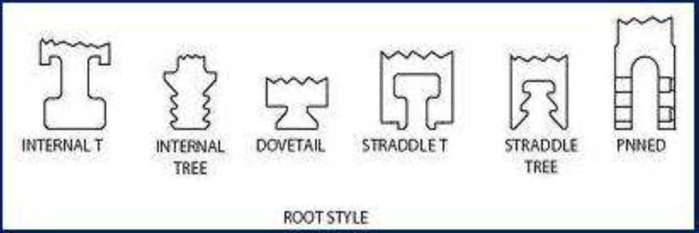
Figure 6.1 Root Style
When the turbine rotor is rotating at high speed the blades will be subjected to considerable centrifugal force and variations in steam velocity across the blades will result in blade vibration. Expansion and contraction will also occur during turbine operation; therefore a means of firmly securing the blades to the wheel is essential. A number of different designs have been employed (Figure). Fitting the blades involves placing the blade root into the wheel through a gate or entrance slot and sliding it into position. Successive blades are fitted in turn and the gate finally closed with a packing piece which is pinned into place. Shrouding is then fitted over tenons on the upper edge of the blades. Alternatively, lacing wires may be passed through and brazed to all the blades. Various root fixing shapes have been developed for turbine blading to suit both construction requirements and conditions under which turbines operate. The most popular types of blade root fixing available are: ¨ Grooves ¨ Straddle ¨ Rivet Groove construction The groove type of root fixing fits into a machined grove around the circumference of the rotor wheel or disc. Blade roots are installed through the closing blade window and then slid around the circumference of the disc into their desired position. The last blade root is installed in the closing blade opening and secured in position by dowel(s). Straddle construction Straddle construction is where the blade root fits over the machining on the outer periphery of the rotor wheel or disc. Once again with this type of construction the blade roots are installed through the closing blade window slid around the circumference of the disc into position, then the last blade inserted is doweled in the closing blade window location. Rivet construction Rivet construction is where the blade root either inserts into a groove or straddles the disc and all blades are doweled into position. Peripheral blade fixing On larger blading where the blade length is relatively long a system of lacing wire or shroud rings are installed to give the blading additional support and reduce vibration. The lacing wire is installed a small distance from the outer ends of the blades while the shroud rings are fitted to tangs on the outer edges of the blades and secured by peening the tangs. DIAPHRAGMS
A fixed blade assembly is very important for turbine blading. It is also known as diaphragm. Only impulse turbines have diaphragms. Partitions between pressure stages in a turbine's casing are called diaphragms. Diaphragms are circular plates made up of two semi-circular halves. A central semi-circular hole in each is provided for the shaft to pass through. One-half of the diaphragm is fitted into the top of the casing, the other half into the bottom. They hold the vane-shaped nozzles and seals between the stages. The nozzles are housed in the diaphragm around its periphery. The central hole in the diaphragm is arranged with projections to produce a labyrinth gland around the shaft. Usually labyrinth-type seals are used. Nozzle rings and diaphragms are specifically designed and fabricated to handle the pressure, temperature and volume of the steam, the size of the turbine and the required pressure drop across the stage. The nozzles used in the first stage nozzle ring are cut from stainless steel. Steam passages are then precision milled into these nozzle blocks before they are welded together to form the nozzle ring. NOZZLES Nozzles serve to convert the high pressure and high energy of the steam into a high-velocity jet of steam with a reduced pressure and energycontent. The steam inlet nozzles are arranged in several groups with all but the main group having control valves. In this way the power produced by the turbine can be varied, depending upon how many nozzle control valves are opened. Both impulse and reaction turbines have steam inlet nozzles. The nozzles in the intermediate pressure stages are formed from profiled stainless steel nozzle sections and inner and outer bands. These are then welded to a circular center section and to an outer ring then precision machined. The low-pressure diaphragms in condensing turbines are made by casting the stainless nozzle sections directly into high-strength cast iron. This design includes a moisture catching provision around the circumference which collects released moisture and removes it from the steam passage. Additional features such as windage shields and inter-stage drains are used as required by stage conditions to minimize erosion. All diaphragms are horizontally split for easy removal and alignment adjustment.
EXERCISES
|
Последнее изменение этой страницы: 2019-03-30; Просмотров: 362; Нарушение авторского права страницы