|
Архитектура Аудит Военная наука Иностранные языки Медицина Металлургия Метрология Образование Политология Производство Психология Стандартизация Технологии |
|
|
Архитектура Аудит Военная наука Иностранные языки Медицина Металлургия Метрология Образование Политология Производство Психология Стандартизация Технологии |
Тема 5. High Frequency (VHF) communication.Стр 1 из 9Следующая ⇒
Тема 5. High Frequency (VHF) communication. КВ-радиостанции. Цель лекции: Изучение КВ-радиостанций. Вопросы лекции: 5.1. Назначение; 5.2. КВ радиостанции «Микрон», «Ядро-1А»; 5.3. High Frequency (VHF) communication; 5.4. HF communications В737 и А320; Назначение. КВ радиостанции (радиостанции ВЧ-связи) предназначены для двусторонней радиотелефонной и радиотелеграфной дальней связи экипажа самолета с наземными службами аэропортов. Диапазон частот ВЧ-связи 2-30 МГц, шаг настройки 1000 Гц (28000каналов). На ЛА устанавливают 1 или 2 комплекта аппаратуры.
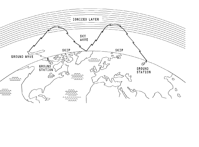
HF communications В 737 и А 320. Подробно рассматривается соответственно в [3] и [5] рекомендуемой литературы. General The high frequency (HF) communication system supplies voice communication over long distances. It gives communication between airplanes or between ground stations and airplanes. The HF system operates in the aeronautical frequency range of 2 MHz to 29.999 MHz. The system uses the surface of the earth and an ionized layer to cause a reflection (skip) of the communication signal. The distance between skips changes due to the time of day, radio frequency, and airplane altitude.
Abbreviations and Acronyms · ACARS - aircraft communications addressing and reporting system · ACP - audio control panel · AM - amplitude modulated · AME - amplitude modulation equivalent · ARINC - Aeronautical Radio Incorporated · BITE - built-in test equipment · comm - communication · EE - electronic equipment · EEC - electronic equipment compartment · FDR - flight data recorder · FDRS - flight data recorder system · freq - frequency · HF - high frequency · I/C - interphone communication · LCD - liquid crystal display · LED - light emitting diode · LRU - line replaceable unit · mic - microphone · PSEU - proximity switch electronics unit · PTT - push-to-talk · RCP - radio communication panel · REU - remote electronics unit · RF - radio frequency · R/T - receive/transmit · SELCAL - selective calling • sq – squelch sql - squelch · SSB - single side band · USB - upper side band · VSWR - voltage standing wave ratio · xmit – transmit
General The HF communication system supplies the flight crew with long range voice communication. The HF communication system can be used to communicate between airplanes and between airplanes and ground stations. The HF communication radio uses frequency select and control signals to transmit and receive voice communication. The HF radio modulates an RF carrier signal with voice audio from the flight interphone system. During the receive mode, the HF radio demodulates the RF carrier signal. This isolates the voice audio from the RF signal. The HF transceiver sends the audio to the flight interphone system. System Components The HF communication system has two HF radios. These are the components: · Radio communication panel · HF transceiver · HF antenna coupler · Common or shared HF antenna. The radio communication panel (RCP) supplies selected frequency information and control signals to tune the HF transceivers and make radio selections. You can use the RCP to select amplitude modulated (AM) or upper side-band (USB) operation. Use the RF sensitivity control to improve HF reception. The RCPs can select and control the frequency of any HF communication radio. The HF transceiver transmits and receives information. The transceiver transmit circuits use flight interphone audio to modulate an RF carrier signal. This voice information goes to other airplanes and ground stations. The receive circuits demodulate the received RF carrier signal to isolate the audio. The received audio is used by the flight crew or other airplane systems. The HF antenna coupler matches the antenna impedance to the transceiver output over the HF frequency range. During the transmit mode, the antenna coupler receives modulated RF from the transceiver and sends it to the antenna. During the receive mode, the antenna coupler receives modulated RF from the antenna and sends it to the transceiver. The HF antenna transmits and receives audio modulated RF signals. External Interface The HF communication system connects with these components/systems:
· Remote electronics unit (REU) · SELCAL decoder unit · Air/ground relay · Flight data acquisition unit (FDAU). System Operation The control panel sends selected frequency information and control signals to the transceiver. The audio control panel sends these signals to the REU: · HF radio select signal · Receive volume control · Push-to-talk (PTT).
During transmit, microphone audio and PTT signals go to the HF transceiver through the REU. The transceiver uses the microphone audio to modulate an RF carrier signal generated in the transceiver. The transceiver sends the modulated RF signal through the antenna coupler to the antenna for transmission to other airplanes and ground stations. Also during transmit, the flight data acquisition unit receives a PTT signal from the transceiver. The flight data acquisition unit uses the PTT for key event marking to record the transmit event. During receive, the antenna receives a modulated RF signal and sends it through the antenna coupler to the transceiver. The transceiver demodulates or isolates the audio from the RF carrier. The received audio goes from the HF transceiver to the flight interphone speakers and headsets through the REU. The SELCAL decoder unit receives audio from the HF transceiver. The SELCAL decoder unit monitors the audio for SELCAL calls that come from the ground station. The HF transceiver receives an air/ground discrete. The HF transceiver uses the discrete to calculate flight legs for internal fault memory.
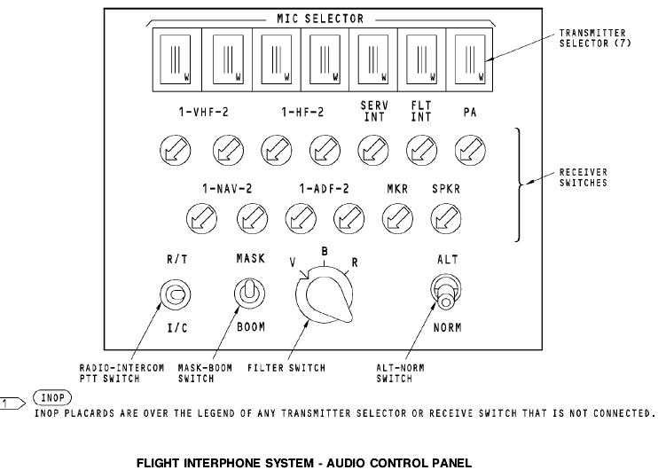
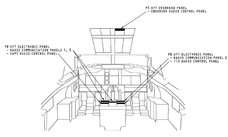
Flight Compartment The radio communication panels are on the P8 aft electronics panel. The audio control panels (ACPs) are part of the flight interphone system. The ACPs have an interface with the HF communication system through the REU. The captain and first officer ACPs are on the P8 aft electronics panel. The first observer ACP is on the P5 aft overhead panel.
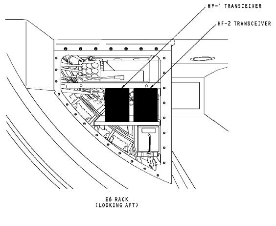
The HF transceivers are on the E6-2 shelf.
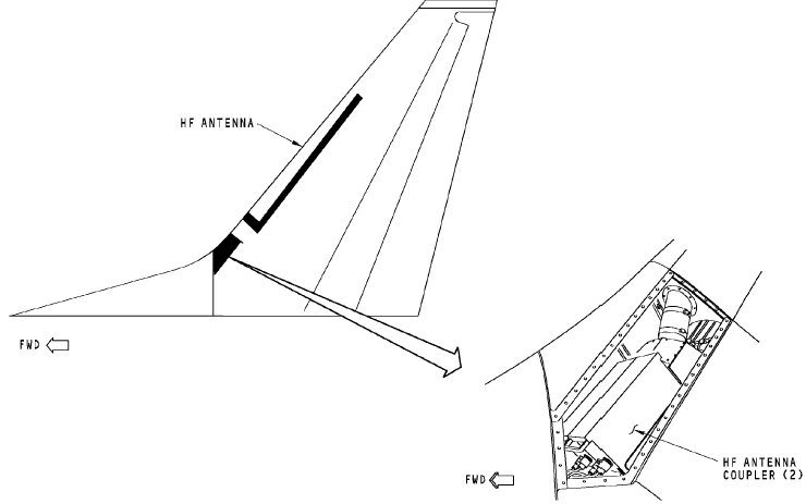
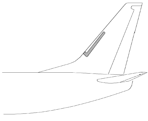
ANTENNA COMPONENT LOCATIONS General The antenna couplers are inside the vertical stabilizer. WARNING: MAKE SURE PERSONNEL STAY A MINIMUM OF SIX FEET (TWO METERS) AWAY FROM THE VERTICAL STABILIZER WHEN THE HF SYSTEM TRANSMITS. RF ENERGY FROM THE HF COMMUNICATION ANTENNA CAN CAUSE INJURIES TO PERSONNEL.
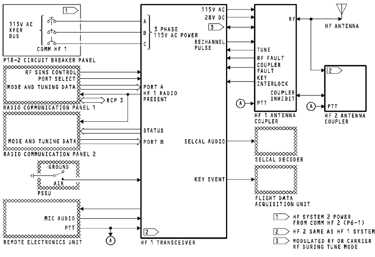
Power The 115v ac transfer (XFR) bus supplies three-phase power to the HF transceiver. The transceiver supplies 115v ac and 28v dc power to the HF antenna coupler. HF Transceiver The HF transceiver has an interface with these components: · RCP 1, 2, and 3 · Selective calling (SELCAL) decoder · Remote electronics unit (REU) · HF antenna coupler · Flight data acquisition unit · Proximity switch electronics unit (PSEU). Radio Communication Panel RCP 1 supplies frequency information to the HF 1 transceiver on an ARINC 429 bus to port A and to the HF 2 transceiver on port B. RCP 2 supplies frequency information to the HF 1 transceiver on an ARINC 429 bus to port B and to the HF 2 transceiver on port A. For more information about tuning interfaces, see HF Communication System - Tuning Interfaces. The HF transceiver supplies the condition of the transceiver to the radio communication panels. The condition of the transceiver is one of the two: OK or FAILED. The radio communication panel supplies these to the HF transceiver: · Amplitude modulated or single side-band control · Tuning data · Port select discrete.
RADIO COMMUNICATION PANEL Antenna Couplers The antenna couplers supply these to the transceivers: · Key interlock · Tune in progress · Received RF · RF fault · Coupler fault.
The antenna coupler opens the key interlock discrete to stop the transceiver transmit mode. The coupler sends the tune in progress discrete to request tuning power from the transceiver. The RF fault is sent to the transceiver when the coupler detects a fault external to the coupler. The coupler sends the coupler fault discrete to the transceiver when it detects an internal failure. Received RF from the antenna is sent to the transceiver during receive mode. The antenna couplers share one common HF antenna. During the transmit mode, only one coupler has an electrical interface with the antenna. The on-side coupler sends the off-side coupler an inhibit discrete to prevent the off-side radio from transmitting. The couplers supply transmitted RF to theantenna. They receive push-to-talk (PTT) from the REU to enable the the coupler tune mode.
The HF transceiver supplies these to the antenna coupler: · Transmitted RF · RF carrier during tune mode · Rechannel pulse. Modulated RF is sent to the antenna through the antenna coupler to be ransmitted. During tune mode, a low wattage RF carrier signal is sent to the coupler to match impedance between the transceiver and the antenna. The transceiver sends the rechannel pulse to start the coupler home sequence mode. HF Antenna The HF antenna receives an RF signal from the antenna coupler and transmits the RF signal to other airplane and ground HF communication systems. The antenna also receives incoming RF signals and sends the RF signals to the antenna coupler. External Interfaces The HF transceiver has an interface with these components from other airplane systems: · Remote electronics unit (REU) · Selective calling (SELCAL) decoder · Flight data acquisition unit · PSEU.
The remote electronics unit sends flight crew microphone (mic) audio to the transceiver to be transmitted. It also sends a PTT to start the transceivers transmit mode. The transceiver sends side tone and received audio to the REU for the flight interphone system. The transceiver sends received audio to the SELCAL decoder. The SELCAL decoder isolates the SELCAL code from voice audio. The flight data acquisition unit receives a PTT from the transceiver for key event marking. The PSEU tells the HF transceiver whether the airplane is on the ground or in the air.
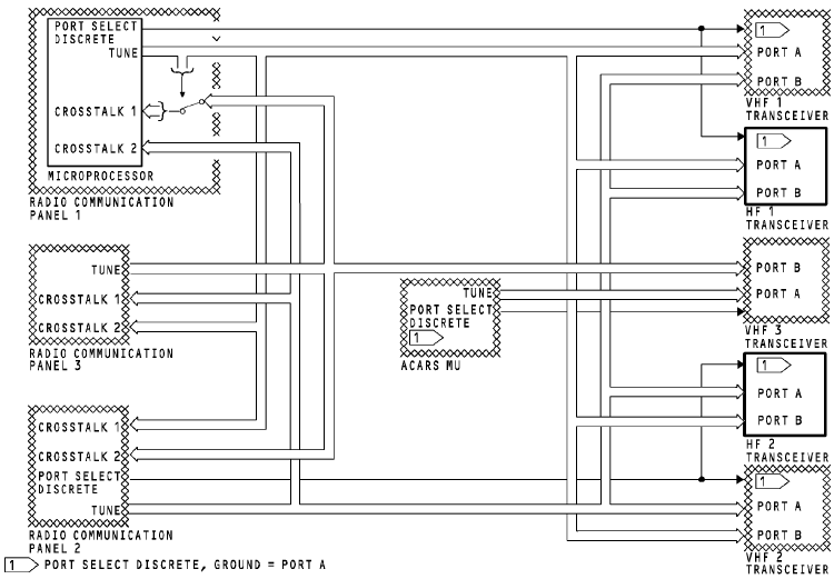
TUNING INTERFACES General The HF communication system uses data buses to share tuning information between the radio communication panels (RCPs) and the communication transceivers. Tuning Bus Each RCP has one ARINC 429 output bus. The RCPs send tuning data to the communication transceivers. Any RCP can tune any transceiver. Each RCP sends tuning data and status to the other radio communication panels. This keeps the tuning data synchronized and lets any RCP tune any transceiver. The RCP keeps the tuning data in memory. Usually, the RCP uses the tuning data from its memory to send on the output bus. The RCP connects the CROSSTALK 1 bus directly to the output bus. This occurs for these RCP conditions: RCP does not have power · RCP is OFF · RCP is failed.
Port Select Discrete RCP 1 and 2 send the port select discretes to the transceivers. Each transceiver has two tuning data input ports, port A and port B. The transceiver uses the port select discrete to select the input port. A grounded port select discrete causes the transceiver to use port A. An open port select discrete causes the transceiver to use port B. Training Information Point If RCP 1 fails, you can tune the HF 1 transceiver with RCP 2 or 3. RCP 1 port select discrete changes from ground to open, and RCP 2 sends tuning data to input port B. RCP 3 sends tuning data on CROSSTALK 2 bus which is connected to RCP 2. RCP 2 connects this tuning data to the output TUNE bus. If RCP 2 fails, you can tune the HF 2 transceiver with RCP 1 or 3. RCP 2 port select discrete changes from ground to open, and RCP 1 sends tuning data to input port B. RCP 3 sends tuning data on CROSSTALK 1 bus which is connected to RCP 1. RCP 1 connects this tuning data directly to the output TUNE bus.
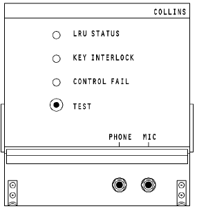
Purpose The HF communication transceiver transmits and receives RF signals for voice communication. Physical Description The front panel has these components: · Three fault LEDs A TEST push-button · A microphone jack · A headphone jack.
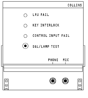
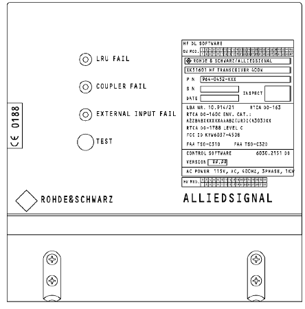
All electrical connections are through connectors at the causes the transceiver. Power The transceiver must have 115 volts, 400 Hz, 3 phase ac power to operate. Transceiver RF output is 400 watts peak envelope power (PEP) in the single sideband (SSB) mode. It is 125 watts average in the amplitude modulated (AM) mode. In the AM mode the tranceiver transmits the amplitude modulation equivalent (AME). AME is the carrier frequency plus the upper side band. Indications The LRU STATUS LED comes on red for a failure in the HF transceiver. The KEY INTERLOCK LED comes on red when the transceiver keys and there is a failure in the HF coupler. Transmission is not possible at this time. The CONTROL FAIL LED comes on red if there is no input from the control panel or if the control panel input goes invalid. The COUPLER FAIL LED comes on red when there is a failure in the HF coupler. Transmission is not possible at this time. The CONTROL INPUT FAIL LED comes on red if there is no input from the control panel or if the control panel input goes invalid. The EXTERNAL INPUT LED comes on red if there is no input from the control panel or if the control panel input goes invalid.
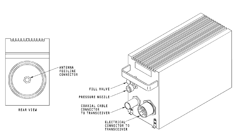
ILF 542
BITE Push the SQL/LAMP TEST push button to stop the operation of the squelch circuit and to hear background noise through the headphones. This test also grounds the RF sensitivity and makes the front panel LEDs come on. Push the TEST push button to test the transceiver front panel LEDs and to start a self-test. Connect a headphone to the transceiver front panel microphone jack to hear two short tones, and after one second, one additional tone through the audio system. HF ANTENNA COUPLER Purpose The HF antenna coupler matches the transceiver 50 ohm impedance output to the antenna impedance at the set frequency. This decreases the voltage standing wave ratio --уменьш. Коэф. (VSWR) to less than 1.3: 1. Physical Description The coupler front panel has these components: · Electrical connector to transceiver · Coaxial connector to transceiver · Pressure nozzle. · The rear panel has the antenna feedline connector. Operation The coupler uses 115v ac to operate. It does not need special cooling. Training Information Point CAUTION: YOU MUST PREPARE EACH HF COUPLER FOR REMOVAL. IF YOU DO NOT PREPARE FOR THE REMOVAL, YOU CAN CAUSE DAMAGE TO THE INTERNAL PARTS OF THE HF ANTENNA COUPLER. CAUTION: MOVE THE HF ANTENNA COUPLER CAREFULLY. SET THE COMPONENT ON ITS BOTTOM. DO NOT SET THE COMPONENT ON ITS END (WITH THE HANDLE UP). INTERNAL PARTS ARE EASILY DAMAGED. It is important to position the antenna coupler tuning elements to the home position before you move the coupler. This will prevent damage to the coupler internal parts.
HF ANTENNA Purpose The HF antenna radiates and receives the RF signal. Physical Description The HF antenna is a notch type antenna. It is a U-shaped fiberglass material. The antenna is sealed within the leading edge of the vertical stabilizer. The antenna receives the feed line from the antenna coupler. WARNING: MAKE SURE PERSONNEL STAY A MINIMUM OF SIX FEET AWAY FROM THE VERTICAL STABILIZER WHEN THE HF SYSTEM TRANSMITS. RF ENERGY FROM THE HF COMMUNICATION ANTENNA CAN CAUSE INJURIES TO PERSONNEL.
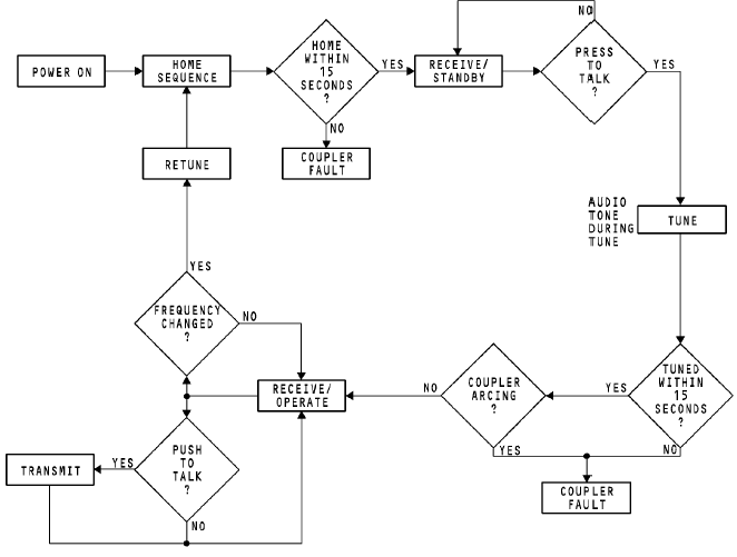
HF FUNCTIONAL MODES General The HF communication system uses an antenna coupler to keep a 50 ohm impedance match between the transceiver and the antenna. This impedance match decreases reflected power through the RF output circuit back to the transceiver. The HF communication system uses functional modes to complete the receive, tune, and transmit operation. These are the HF communication system functional modes: · Home · Receive/standby · Tune · Receive/operate · Transmit.
The HF system controls the modes in sequence. The modes do --послед-ть, очередность not change until all necessary conditions for the modes occur. --произошли Home Mode The home mode starts at power-up or when a new frequency is set. The transceiver sends a rechannel pulse to the coupler to start the home mode. The antenna tuning elements in the coupler move to the home position. The elements are in a position for minimum attenuation of incoming signals. It is important that the antenna tuning elements inside the coupler be in the home position before you move the coupler. If you move the coupler before the tuning elements are in the home position, damage to internal parts can occur. Receive/Standby Mode The receive/standby mode starts when the antenna tuning elements are in the home position. In the receive/standby mode, the HF system can receive RF signals at the set frequency. The system is ready to key for tuning at any time when it receives a PTT from the REU. Tune The tune occurs in these steps: · Tune A (resonance) · Tune B (load) · Tune C (VSWR).
To start tune mode A, key the transceiver. The transceiver microprocessor sets the AM mode and the key is latched. The transceiver sends reduced RF power to the antenna coupler. A 1 kHz tone can be heard at the transceiver mic jack or through the flight interphone system as the tuning occurs. The antenna coupler tunes in 2 to 4 seconds. The antenna coupler discriminator circuit operates to set phase differences between the RF voltage and current. The antenna coupler tuning elements are set for zero phase difference. During tune mode B, tuning elements are set to a total impedance of 50 ohms or less and resonant. During tune mode C, the tuning elements move so that the RF power load makes a VSWR less than 1.3: 1. The reflected power is less than 2 watts RF. Receive/Operate The receive/operate mode occurs when tune mode C is complete. The key latch is removed. The tuning RF power from the transceiver is tuned off, and the 1 kHz tone stops. The system is ready for reception or transmission. Transmit The pilot keys the microphone to transmit. The coupler adjusts tuning elements to keep VSWR less than 1.3: 1 during modulated transmission. The audio tone through the flight interphone system does not sound at this time.
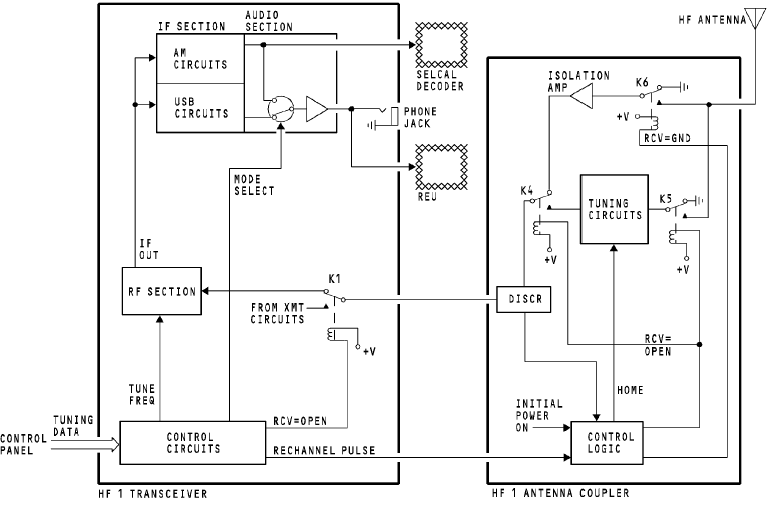
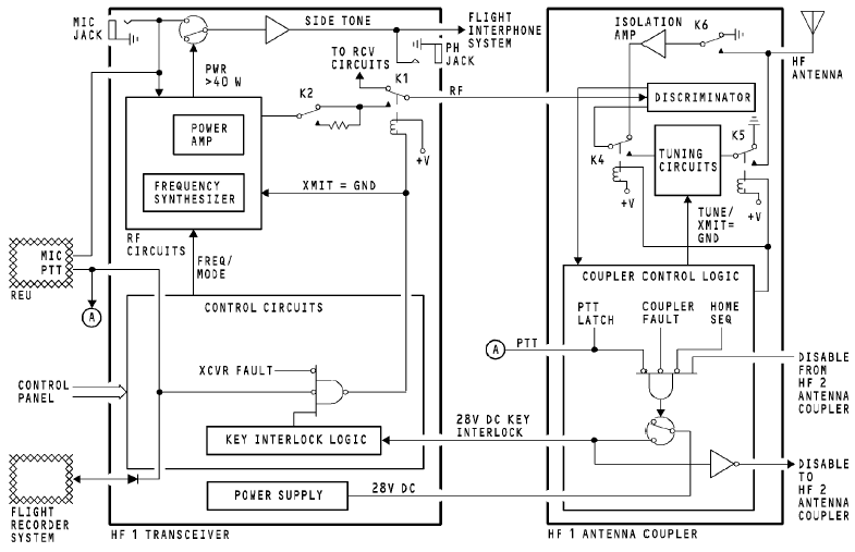
General During the home mode, the antenna coupler tuning circuits are adjusted for minimum antenuation of the incoming RF signal. This is called the tuning circuit home position. The tuning circuits are adjusted to the home position at the start of every new tune cycle and at power up. The HF communication system can receive audio modulated RF after the tuning circuits are in the home position and the HF system goes to receive/standby mode. Home Mode The control panel sends tune and modulation mode (AM or USB) data to the HF transceiver control circuits. When the control panel sends a change in frequency, the transceiver control circuits send a rechannel pulse to the antenna coupler control logic. This causes the coupler to begin the home sequence mode. The home mode also starts at power up. During the home mode, the coupler control logic has these functions: · Tells the tuning circuits to go to the home position · Energizes relay K6 · De-energizes relays K4 and K5.
The control logic energizes K6 so that the HF system can receive during home mode. When the tuning elements are in the home position, the HF system goes to the receive/standby mode. Receive/Standby Mode During the receive/standby mode, relay K1 in the transceiver and K4 and K5 in the coupler de-energize. Relay K6 energizes. Incoming RF signals go to an isolation amplifier and a discriminator in the coupler. The RF output from the coupler goes to the RF section of the transceiver. The RF section has these functions: · Amplifies the RF signal · Mixes, filters, and processes the RF signal to make an intermediate frequency (IF) output.—ПЧ
The AM and the USB circuits in the IF section amplify the IF signal and detect the audio from the signal. The AM section sends the audio to the SELCAL decoder and to a solid state switch. Audio from the USB detector also goes to this switch. The mode select output, from the transceiver control circuits, selects audio from either the AM section or the USB section. The mode select output audio goes through an amplifier to these two points: · A phone jack on the transceiver front panel · The flight interphone system.
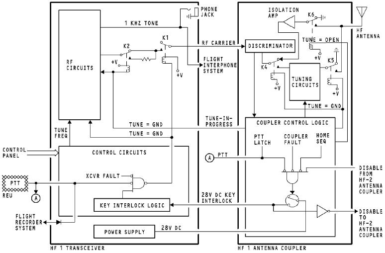
TUNE FUNCTIONAL DESCRIPTION General The HF 1 and HF 2 systems are the same. This example shows the HF 1 system. Before the HF communication system can transmit, the antenna coupler must be tuned to match the impedance between the transceiver and the antenna. The antenna coupler tune circuits keep the impedance at 50 ohms over the HF frequency range. The tune sequence begins with the first push-to-talk (PTT) after the tune circuits are in the home position, and the HF system is in the receive/standby mode. Tune Mode Initiation --включение Select the HF communication frequency on the control panel and key the mic. The mic sends a PTT signal through the REU to start the tune sequence. The same PTT goes to the control circuits in the transceiver and the control logic circuits in the antenna coupler. The coupler control logic latches the PTT(замыкает, запирает) discrete to ground until the tuning is complete. The coupler control logic energizes relays K4 and K5, and deenergizes relay K6. The coupler control logic sends a key interlock signal to the HF transceiver. It also sends a disable (запрещающий) discrete to the off-side antenna coupler to keep the off-side HF system from transmitting. The coupler control logic can start tuning only in these conditions:
· There is a ground on the PTT line · There is no disable from the HF 2 coupler · The home sequence is complete · There are no coupler faults.
Tune Mode Operation The coupler control logic sends a tune-in-progress discrete to (идет настройка) the transceiver when the coupler is in tune mode. This tune-in-progress discrete tells the transceiver to send a RF carrier (несущую) tuning signal to the coupler. The tune-in-progress discrete energizes relay K2 in the transceiver. It also goes to the transceiver RF circuits. The RF circuits send a 1 kHz audio tone to the front panel phone jack and to the flight interphone system. This tone tells the operator that the system is in the tune mode. The control circuits in the transceiver energize relay K1 and tell the RF circuits to send an RF carrier in these conditions: · There is a PTT signal · There is no transceiver fault · There is a key interlock signal from the coupler.
In the tune mode, the RF carrier contains no audio. The carrier goes to relay K2. Because relay K2 energizes in the tune mode, the output goes through the resistor. The resistor reduces the power to 75 watts. Relay K1 energizes in the tune mode and the RF carrier goes to the coupler. The RF carrier goes through the discriminator, energized relay K4, the tuning elements, and energized relay K5 to the antenna. During the tune mode, the discriminator samples the RF carrier and sends analog signals to the coupler control logic circuits. The control logic circuits use the signals from the discriminator to generate controls for the tuning circuits. The tune mode continues until the impedance of the transceiver and the antenna are in balance for the frequency the flight crew selects. When the impedance balances, the control logic circuits remove these signals: · The tune-in-progress discrete sequence · The ground on the PTT discrete · The 28v dc key interlock signal.
If the tune mode does not end within 15 seconds, the coupler control logic sends a coupler fault to the transceiver. Operate Mode (Receive) When the tune mode ends, the HF system begins the operate (receive) mode. Relays K1 and K2 in the transceiver and K4 and K5 in the antenna coupler de-energize. Relay K6 energizes. The HF system is ready to transmit when it receives a PTT signal. Key Event Output The PTT discrete goes to the flight recorder system for key event marking.
General The HF 1 AND HF 2 systems are the same. This example shows the HF 1 system. When the tune sequence is complete, the HF system goes to the receive/operate mode and is ready to transmit. A PTT discrete starts the operation in the transceiver and antenna coupler. Transmit Mode In the receive/operate mode, the PTT discrete from the REU to the transceiver and coupler control logic circuits starts the transmit mode. The coupler control logic circuits energize relays K4 and K5, and de-energize relay K6. This puts a ground on the input to the isolation amplifier. It connects the tuning elements in-line between the discriminator and the antenna. The coupler control logic sends a ground to disable the off-side coupler. At the same time, it sends a key interlock signal to the HF transceiver. The coupler control logic does this only in these conditions: · There is a ground on the PTT line · There is no disable from the HF 2 antenna coupler · The coupler control logic circuits are not in the home mode · There are no coupler faults.
The control circuits in the transceiver energize relay K1 and tell the RF circuits to transmit a carrier in these conditions: · There is a ground on the PTT line · There is no transceiver fault · There is a key interlock signal from the coupler.
The RF circuits mix the carrier from the frequency synthesizer with the mic audio. The RF signal goes through these: · A power amplifier · The relaxed contacts of relay K2 · The energized contacts of relay K1 · The discriminator in the coupler.
The RF signal then goes through these: · Energized relays K4 and K5 · The tuning elements.
The antenna receives the RF from the tuning elements and transmits it. Side Tone When the output from the transceiver power amplifier is more than 40 watts in the AM mode, a switch connects the microphone audio to an audio amplifier. The amplified audio goes to the audio jack and to the flight interphone system for side tone. When the output is less than 40 watts, there is no side tone. When the output is less than 30 watts, an LRU fault occurs. Key Event Output The PTT discrete goes to the flight recorder system for key event marking.
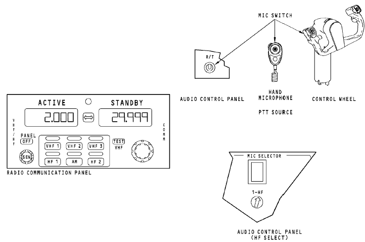
OPERATION General You use these components to operate the HF radio: · Hand microphone or headset · Radio communication panel · Control wheel mic switch · Remote MIC switch · Audio control panel.
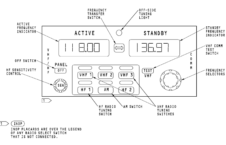
Receive Operation You use the radio communication panel and the audio control panel to receive transmissions on the HF radio. On the audio control panel, push the receiver volume control for the HF radio. Turn the control to adjust the volume from the HF radio. You hear audio on the headset and the flight interphone speakers. To hear sound from the flight interphone speakers, push the speaker (SPKR) volume control to turn on the speaker. Turn the control to adjust the volume of sound from the speaker. Use the on/off control to turn on the radio communication panel. When you first turn it on, the radio communication panel tunes the VHF radio. Push the HF 1 switch to make the radio communication panel tune the HF radio. A light above the switch comes on to show which radio the panel controls. The frequency displays show HF radio frequencies (2.000 to 29.999 MHz). The HF radio uses the frequency in the active frequency display. Use the frequency selectors to tune the radio to a new frequency. The standby frequency display shows the new frequency. When you are sure the frequency is correct, push the frequency transfer switch. The active frequency display shows the new frequency. The HF radio uses the new frequency. NOTE: When you select a new frequency, the HF coupler drives its tuning elements to the home position. Listen for audio from the HF radio on the speaker or headset. Adjust the volume control switches on the audio control panel for a comfortable sound level. Use the HF sensitivity (HF SENS) control on the radio communication panel to adjust the sensitivity of the HF radio receiver. Transmit Operation WARNING: MAKE SURE PERSONNEL STAY A MINIMUM OF SIX FEET AWAY FROM THE VERTICAL STABILIZER WHEN THE HF SYSTEM TRANSMITS. RF ENERGY FROM THE HF COMMUNICATION ANTENNA CAN CAUSE INJURIES TO PERSONNEL. WARNING: DO NOT OPERATE THE HF COMMUNICATION SYSTEM WHILE FUEL IS PUT INTO THE AIRPLANE. INJURY TO PERSONS AND DAMAGE TO EQUIPMENT CAN OCCUR. Make sure the active frequency display shows the frequency you want to transmit. Make sure the frequency you select is a valid transmit frequency. Push the microphone selector switch on the audio control panel for the HF radio. Listen for transmissions on the frequency you selected. When the frequency is clear, push and release the push-to-talk for the microphone. This causes the HF coupler to tune to the transmission frequency. While the coupler tunes, the HF transceiver supplies a 1 kHz tone. You hear this tone on the speaker and in the headset. Normally, it takes several seconds for the coupler to tune. When the 1 kHz tone stops, the HF system is ready to transmit. When the frequency is clear and you want to transmit a message, key the mic and speak into it. You hear sidetone in the headphone and muted sidetone from the flight interphone speaker. The flight interphone system mutes the sidetone to the speaker when you use the boom mic or the hand mic. You can continue to transmit and receive on the frequency you selected. When you select another frequency and key the mic to transmit, the HF coupler tunes again. You hear the 1 kHz tone while it tunes. Non-Normal Indications If you hear the 1 kHz tone for more than 15 seconds when the coupler tunes, there may be a coupler fault. If the tone only lasts as long as you key the microphone, you may have tuned a frequency which is outside the frequency range for the HF transceiver.
Вопросы для самоконтроля. 1. Назначение КВ радиостанций. 2. Состав «Микрон». 3. Основные характеристики «Микрон». 4. Принцип действия «Микрон». 5. Органы управления и регулировки «Микрон». 6. Включение, проверка функционирования «Микрон». 7. Индикация и сигнализация. 8. Назначение КВ радиостанции «Ядро-1А». 9. Состав «Ядро-1А». 10. Основные характеристики «Ядро-1А» 11. Органы управления и регулировки «Ядро-1А». 12. Включение, проверка функционирования «Ядро-1А». 13. Индикация и сигнализация «Ядро-1А». 14. Виды модуляции радиостанции «Микрон». 15. Виды модуляции радиостанции «Ядро-1А». 16. Р\ст. «Ядро-1». Что сигнализирует табло «Настройка». 17. Р\ст. «Ядро-1». Что сигнализирует табло «Авария». 18. Р\ст. «Микрон». Что сигнализирует лампа «Прд.». 19. Р\ст. «Микрон». Что сигнализирует лампа «Настройка». 20. Р\ст. «Микрон». Что сигнализирует лампа «Авария». 21. Р\ст. «Ядро-1». Признак исправности приемного тракта в режиме ВСК. 22. Р\ст. «Ядро-1». Признак исправности передающего тракта в режиме ВСК. 23. Назначение, состав, основные характеристики HF communication В737. 24. Принцип работы HF communication В737. 25. Интерфейс HF communication В737. 26. Включение, проверка функционирования HF communication В737. Рекомендуемая литература. Основная 1. Сосновский А.А., Хаймович И.А. Радиоэлектронное оборудование летательных аппаратов. Справочник – М.: Транспорт, 1987г. 2. Учебное пособие. Радиоэлектронное оборудование ЛА. Составитель Кукушин В.А. Академия ГА, 2007г. 3. Учебное пособие. COMMUNICATION СВЯЗНОЕ ОБОРУДОВАНИЕ BOEING 737-600/700/800/900. Training Manual. Составитель Кукушин В.А. Академия ГА, 2008г. 4. Учебное пособие. NAVIGATION. Part 1. НАВИГАЦИОННОЕ ОБОРУДОВАНИЕ. Часть 1. BOEING 737-600/700/800/900. Training Manual. Составитель Кукушин В.А. Академия ГА, 2008г. 5. Учебное пособие. COMMUNICATIONS СВЯЗНОЕ ОБОРУДОВАНИЕ А-320. Training Manual. Составитель Кукушин В.А. Дополнительная 1. Aircraft Aerodynamic, Structures and Systems. Module 13: M13.04 Communication Navigation (ATA 23/34); M13.06 Equipment and Furnishings (ATA 25) / EASA Part-66 Training Handbook. – LINK& LEARN Aviation Training GmbH, 2007. – 176 p. 2. Эксплуатационная документация на аппаратуру. (Технические описания. Инструкции по эксплуатации. АММ).
Тема 5. High Frequency (VHF) communication. КВ-радиостанции. Цель лекции: Изучение КВ-радиостанций. Вопросы лекции: 5.1. Назначение; 5.2. КВ радиостанции «Микрон», «Ядро-1А»; 5.3. High Frequency (VHF) communication; 5.4. HF communications В737 и А320; Назначение. КВ радиостанции (радиостанции ВЧ-связи) предназначены для двусторонней радиотелефонной и радиотелеграфной дальней связи экипажа самолета с наземными службами аэропортов. Диапазон частот ВЧ-связи 2-30 МГц, шаг настройки 1000 Гц (28000каналов). На ЛА устанавливают 1 или 2 комплекта аппаратуры.
|
Последнее изменение этой страницы: 2019-03-30; Просмотров: 575; Нарушение авторского права страницы