|
Архитектура Аудит Военная наука Иностранные языки Медицина Металлургия Метрология Образование Политология Производство Психология Стандартизация Технологии |
|
|
Архитектура Аудит Военная наука Иностранные языки Медицина Металлургия Метрология Образование Политология Производство Психология Стандартизация Технологии |
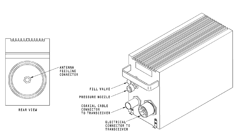
The coupler tunes in the aeronautical frequency range of 2 to
29.999 MHz. Tuning occurs in 2 to 4 seconds, 7 seconds maximum. Training Information Point CAUTION: YOU MUST PREPARE EACH HF COUPLER FOR REMOVAL. IF YOU DO NOT PREPARE FOR THE REMOVAL, YOU CAN CAUSE DAMAGE TO THE INTERNAL PARTS OF THE HF ANTENNA COUPLER. CAUTION: MOVE THE HF ANTENNA COUPLER CAREFULLY. SET THE COMPONENT ON ITS BOTTOM. DO NOT SET THE COMPONENT ON ITS END (WITH THE HANDLE UP). INTERNAL PARTS ARE EASILY DAMAGED. It is important to position the antenna coupler tuning elements to the home position before you move the coupler. This will prevent damage to the coupler internal parts.
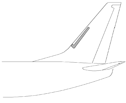
HF ANTENNA Purpose The HF antenna radiates and receives the RF signal. Physical Description The HF antenna is a notch type antenna. It is a U-shaped fiberglass material. The antenna is sealed within the leading edge of the vertical stabilizer. The antenna receives the feed line from the antenna coupler. WARNING: MAKE SURE PERSONNEL STAY A MINIMUM OF SIX FEET AWAY FROM THE VERTICAL STABILIZER WHEN THE HF SYSTEM TRANSMITS. RF ENERGY FROM THE HF COMMUNICATION ANTENNA CAN CAUSE INJURIES TO PERSONNEL.
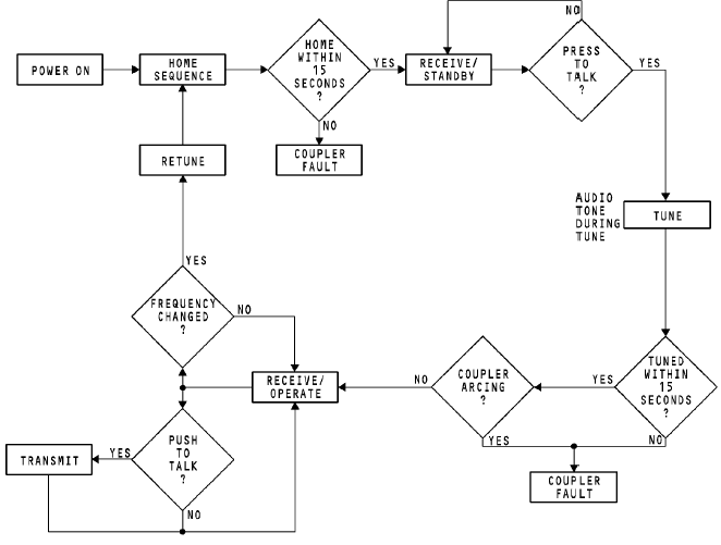
HF FUNCTIONAL MODES General The HF communication system uses an antenna coupler to keep a 50 ohm impedance match between the transceiver and the antenna. This impedance match decreases reflected power through the RF output circuit back to the transceiver. The HF communication system uses functional modes to complete the receive, tune, and transmit operation. These are the HF communication system functional modes: · Home · Receive/standby · Tune · Receive/operate · Transmit.
The HF system controls the modes in sequence. The modes do --послед-ть, очередность not change until all necessary conditions for the modes occur. --произошли Home Mode The home mode starts at power-up or when a new frequency is set. The transceiver sends a rechannel pulse to the coupler to start the home mode. The antenna tuning elements in the coupler move to the home position. The elements are in a position for minimum attenuation of incoming signals. It is important that the antenna tuning elements inside the coupler be in the home position before you move the coupler. If you move the coupler before the tuning elements are in the home position, damage to internal parts can occur. Receive/Standby Mode The receive/standby mode starts when the antenna tuning elements are in the home position. In the receive/standby mode, the HF system can receive RF signals at the set frequency. The system is ready to key for tuning at any time when it receives a PTT from the REU. Tune The tune occurs in these steps: · Tune A (resonance) · Tune B (load) · Tune C (VSWR).
To start tune mode A, key the transceiver. The transceiver microprocessor sets the AM mode and the key is latched. The transceiver sends reduced RF power to the antenna coupler. A 1 kHz tone can be heard at the transceiver mic jack or through the flight interphone system as the tuning occurs. The antenna coupler tunes in 2 to 4 seconds. The antenna coupler discriminator circuit operates to set phase differences between the RF voltage and current. The antenna coupler tuning elements are set for zero phase difference. During tune mode B, tuning elements are set to a total impedance of 50 ohms or less and resonant. During tune mode C, the tuning elements move so that the RF power load makes a VSWR less than 1.3: 1. The reflected power is less than 2 watts RF. Receive/Operate The receive/operate mode occurs when tune mode C is complete. The key latch is removed. The tuning RF power from the transceiver is tuned off, and the 1 kHz tone stops. The system is ready for reception or transmission. Transmit The pilot keys the microphone to transmit. The coupler adjusts tuning elements to keep VSWR less than 1.3: 1 during modulated transmission. The audio tone through the flight interphone system does not sound at this time.
|
Последнее изменение этой страницы: 2019-03-30; Просмотров: 321; Нарушение авторского права страницы