|
Архитектура Аудит Военная наука Иностранные языки Медицина Металлургия Метрология Образование Политология Производство Психология Стандартизация Технологии |
|
|
Архитектура Аудит Военная наука Иностранные языки Медицина Металлургия Метрология Образование Политология Производство Психология Стандартизация Технологии |
Training Information Point
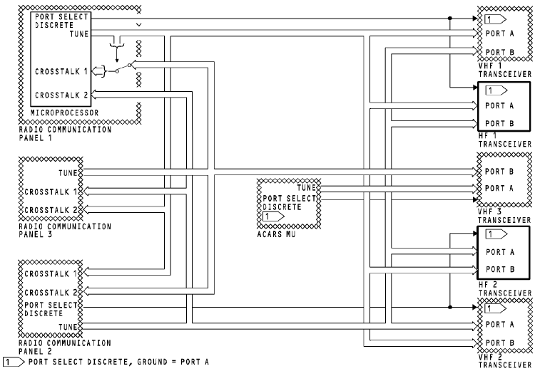
If RCP 1 fails, you can tune the HF 1 transceiver with RCP 2 or 3. RCP 1 port select discrete changes from ground to open, and RCP 2 sends tuning data to input port B. RCP 3 sends tuning data on CROSSTALK 2 bus which is connected to RCP 2. RCP 2 connects this tuning data to the output TUNE bus. If RCP 2 fails, you can tune the HF 2 transceiver with RCP 1 or 3. RCP 2 port select discrete changes from ground to open, and RCP 1 sends tuning data to input port B. RCP 3 sends tuning data on CROSSTALK 1 bus which is connected to RCP 1. RCP 1 connects this tuning data directly to the output TUNE bus.
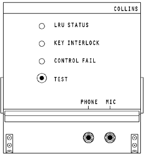
HF COMMUNICATION TRANSCEIVER Purpose The HF communication transceiver transmits and receives RF signals for voice communication. Physical Description The front panel has these components: · Three fault LEDs A TEST push-button · A microphone jack · A headphone jack.
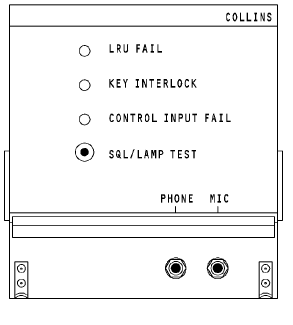
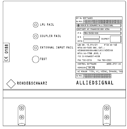
All electrical connections are through connectors at the causes the transceiver. Power The transceiver must have 115 volts, 400 Hz, 3 phase ac power to operate. Transceiver RF output is 400 watts peak envelope power (PEP) in the single sideband (SSB) mode. It is 125 watts average in the amplitude modulated (AM) mode. In the AM mode the tranceiver transmits the amplitude modulation equivalent (AME). AME is the carrier frequency plus the upper side band. Indications The LRU STATUS LED comes on red for a failure in the HF transceiver. The KEY INTERLOCK LED comes on red when the transceiver keys and there is a failure in the HF coupler. Transmission is not possible at this time. The CONTROL FAIL LED comes on red if there is no input from the control panel or if the control panel input goes invalid. The COUPLER FAIL LED comes on red when there is a failure in the HF coupler. Transmission is not possible at this time. The CONTROL INPUT FAIL LED comes on red if there is no input from the control panel or if the control panel input goes invalid. The EXTERNAL INPUT LED comes on red if there is no input from the control panel or if the control panel input goes invalid.
ILF 542
BITE Push the SQL/LAMP TEST push button to stop the operation of the squelch circuit and to hear background noise through the headphones. This test also grounds the RF sensitivity and makes the front panel LEDs come on. Push the TEST push button to test the transceiver front panel LEDs and to start a self-test. Connect a headphone to the transceiver front panel microphone jack to hear two short tones, and after one second, one additional tone through the audio system. HF ANTENNA COUPLER Purpose The HF antenna coupler matches the transceiver 50 ohm impedance output to the antenna impedance at the set frequency. This decreases the voltage standing wave ratio --уменьш. Коэф. (VSWR) to less than 1.3: 1. Physical Description The coupler front panel has these components: · Electrical connector to transceiver · Coaxial connector to transceiver · Pressure nozzle. · The rear panel has the antenna feedline connector. Operation The coupler uses 115v ac to operate. It does not need special cooling. |
Последнее изменение этой страницы: 2019-03-30; Просмотров: 358; Нарушение авторского права страницы