
|
Архитектура Аудит Военная наука Иностранные языки Медицина Металлургия Метрология Образование Политология Производство Психология Стандартизация Технологии |
|
|
Архитектура Аудит Военная наука Иностранные языки Медицина Металлургия Метрология Образование Политология Производство Психология Стандартизация Технологии |
Electronic Chart Display and Information SystemСтр 1 из 14Следующая ⇒
Electronic Chart Display and Information System
(ECDIS) Manual
RECORDS OF CHANGES
S ect i on | P a ge |
Dat e |
D e sc ription |
Sign. | |||||||||
| N o. |
|
|
|
| |||||||||
| 1. | Appendix V | 01.12.2010 | Introduction of form to be issued by on board after familiarization of new joiner | Compliance | |||||||||
| 2 | All Sections | 01.04.2011 | To accommodate changes for Dual ECDIS on board and Paperless Navigation | Compliance | |||||||||
| 3. | 1.16 | 01.08.2011 | Training For Navigating Officers- Overall Aspect | Compliance | |||||||||
| 4 | 1.1; 1.3; 1.9; 1.10; 1.12.2; 1.12.3; 1.14.5; 1.14.7 1.17; 1.18 | 01.08.2012 | IHO data presentation & display checks; ECDIS integration; Alarms & Indicators; Setting Safety depth and Safety contour alarms; Alarm setting adjustments; Safety parameters and minimum settings; Sensory input failure; GPS signal to Noise Ratio; ECDIS linking; Preparing passage plan T&P notices & Nav warnings; Appraisal & Planning tips; Execution and monitoring tips; Authorization for verification of ENC; Electronic Chart Correction; Record of updates | Compliance | |||||||||
| 5 | Appendix VIII |
| 17.09.2013 | Added new appendix for ECDIS Contingency | Compliance | ||||||||
|
|
| Plan(Ship Specific) |
|
| |||||||||
| 6 | Appendix III | 01.06.2015 | Updated Flag State ECDIS Requirements | Compliance | |||||||||
| Objectives, 1.3, 1.9, 1.14.5
| 01.06.2015 | Updated references to Marine Manual and Appendices. | Compliance | ||||||||||
| 1.16 | 01.06.2015 | Training requirements amended as per Industry and flag guidelines. No trickle down training. | Compliance | ||||||||||
| 1.8 | 01.06.2015 | Operating with ECDIS – Masters Standing Orders. | Compliance | ||||||||||
|
|
| 1. |
| ||||||||||
| 7 | Sect 1.1, 1.4, 1.10, 1.11, 1.12, 1.13, Appendix 8, Appendix 3, |
| 2. 1. Procedure included on safety settings to be made. 3. 2. Removed section on contingencies and reference made to ERM 4. 3. Amended Appendix 8 on contingencies 5. 4. Added new CATZOC chart sect 1. 6. 5. Removed sect 1.11 on Emergency procedures 7. 6. Appendix 3 – Flag circulars table removed and referenced to Supplementary 8. docs 9. 7. Added new table for Symbols in sect 1.4 10. 8. IHO ECDIS standards updated sect 1.1 11. 9. Added procedure for crossing the safety contour sect 1.11
| RCC | |||||||||
|
|
|
|
| ||||||||||
TABLE O F CONTENTS
| A | SEC TION |
| I | Introduction |
| II | Objectives |
| III | Approval |
| SE CTION 1 | T HE OPERATION OF ELECTRONIC CHARTS |
| 1.1 | Types of Electronic Charts |
| 1.2 | Limitations of ECDIS |
| 1.3 | Alarms and Indications |
| 1.4 | Symbols & information display |
| 1.5 | Back-up |
| 1.6 | Main components of ECDIS |
| 1.7 | Standard ECDIS functions |
| 1.8 | Operating ECDIS |
| 1.9 | ECDIS safety |
| 1.10 | Safety Settings |
| 1.11 | Crossing the safety Contour |
| 1.12 | CATZOC table |
| 1.13 | ECDIS failure |
| 1.14 | Using ECDIS with other instruments |
| 1.15 | Possible problems. |
| 1.16 | Passage Planning |
| 1.17 | Precautions against Virus |
| 1.18 | Training of Navigating Officers |
| 1.19 | Licensing |
| 1.20 | Electronic Chart Correction |
| 1.21 | PMS |
| A PPE NDIX 1 | IMPLEMENTATION S CHEDULE OF IMO ECDIS REQUIREMENTS |
| A PPE NDIX 2 | F A CTS ABOUT ELECTRONIC CHARTS AND CARRIAGE REQUIREMENTS |
| A PPE NDIX 3 | F L A G STATE ECDIS REQUIREMENTS |
| A PPE NDIX 4 | S HIP SPECIFIC EQUIPMENT MANUFACTURER USER MANUAL |
| A PPE NDIX 5 | E CDIS ON BOARD TRAINING RECORD; ONBOARD FAMILIARSIATION CHECKLIST |
| A PPE NDIX 6 | IHO ENC / ECDIS Data presentation test |
| A PPE NDIX 7 | L E G ISLATION, S T A NDARDS AND IMO RESOLUTIONS |
| APPENDIX 8 | ECDIS Contingency plan |
I. Introduction
ECDIS, which stands for Electronic Chart Display and Information System, is an on-board electronic chart system that conforms to the SOLAS requirements for use as a primary method of navigation and which complies with the standards of the IMO and the specifications of the IHO. The main purpose of an ECDIS is to make navigation safer by using its computerised ability to continuously show the position of the vessel carrying it in relation to land, charted objects, aids-to-navigation and navigational hazards, along with providing other useful navigational information.
IMO's definition of an ECDIS is that it is 'a navigation information system which with adequate back-up arrangements can be accepted as complying with the up-to-date chart requirement of regulation V/19.2 of the 1974 SOLAS Convention, by displaying selected information from a system electronic navigational chart (SENC) with positional information from navigation sensors to assist the mariner in route planning and route monitoring, and if required display additional navigation-related information.'
Of the many commercial electronic chart systems available, only those which qualify as an ECDIS by meeting the standards of the IMO and the specifications of the IHO, and which are approved by a national administration, satisfy SOLAS carriage requirements and are therefore officially permitted to be used for primary navigation.
II. Objectives
The objective of preparing this Manual is to provide Bridge Watch Keeping officers with information that includes company requirements and ship specific equipment requirements in a single document for ease of familiarization by the users and thereby promote safe navigation. The information contained in this manual supplements the Company procedures for safe navigation given in Marine Manual and the Appendix to the manual.
III. Approval
This Manual has been approved by the LPSQ Director. The guidance provided within this manual is intended for all BSM ships and applicable to all SMC.
Types of Electronic Charts
G e neral
There are two basic types of electronic chart systems. Those that comply with the IMO requirements for SOLAS class vessels, known as the Electronic Chart Display and Information System (ECDIS), and all other types of electronic chart systems, regarded generically as Electronic Chart Systems (ECS). If an ECS is carried on board, the continuous use of up-to-date paper charts remains essential for safe navigation and to fulfill carriage requirements.
To satisfy the chart carriage requirements of SOLAS Chapter V, ECDIS must use Electronic Navigational Charts ENCs. These are vector charts produced to International Hydrographic Organization standards and officially issued by or on the authority of a Government authorized Hydrographic Office or other relevant government institution. At present, ENC data is not available world-wide which limits the use of ECDIS in some areas. This situation, however, is rapidly changing and comprehensive ENC coverage of the world's major trading routes and ports is forecast to be completed in the near future.
The ENC contains all the chart information necessary for safe navigation, and may contain supplementary information in addition to that contained in the paper chart (e.g. sailing directions) which may be considered necessary for safe navigation.
On l y ENC are permitted to be used for navigation. Should ENC not be available for sections of the intended voyage then the vessel must use an up-to-date paper folio of corrected charts for navigation.
ENC
The ENC is a database of individual items of digitized chart data which can be displayed as a seamless chart. ENCs of appropriate detail are provided for different navigational purposes such as coastal navigation, harbor approach and berthing. The amount of detail displayed is automatically reduced when the scale of a particular ENC is reduced, in order to lessen clutter. Individual items of data can be selected and all relevant information will be displayed (for instance, all the available information relevant to a light or navigation mark).
ENCs are therefore very much more than an electronic version of the paper chart. With vector charts the data is “layered”, enabling the user to de-select certain categories of data, such as textual descriptions, which may clutter the display and may not be required at the time. It is also possible for the user to select a depth contour so providing an electronic safety contour which may automatically warn the watch-keeper when approaching shallow water. Mariners should use the facility to de-select data with extreme caution as it is possible accidentally to remove data essential for the safe navigation of the vessel.
RNC
The Raster Chart Display System (RCDS) uses RNCs, which are exact facsimiles of official paper charts, and for which Hydrographic Offices take the same liability as for their paper products. RCDS does not have the same functionality as ECDIS and thus an up-to-date folio of paper charts for areas not covered by ENC must be maintained for the intended voyage.
E CDIS Standards
ECDIS in operation comprises hardware, software and data. It is important for the safety of navigation that the application software within the ECDIS works fully in accordance with the Performance Standards and is capable of displaying all the relevant digital information contained within the ENC.
Any ECDIS which has not been upgraded to be compliant with the latest version of the ENC Product Specification or the S-52 Presentation Library may be unable to correctly display the latest charted features. Additionally the appropriate alarms and indications may not be activated even though the features have been included in the ENC. Similarly any ECDIS which is not updated to be fully compliant with the S-63 Data Protection Standards may fail to decrypt or to properly authenticate some ENCs, leading to failure to load or install.
ECDIS that is not updated for the latest version of IHO Standards may not meet the chart carriage requirements as set out in SOLAS regulation V/19.2.1.4.
The master must verify via the vessel’s superintendent that the ECDIS software installed is the latest version and in compliance with the standards. The superintendent is to seek clarification with the ECDIS manufacturer.
The IHO Standards that relate to ECDIS, ENC production and distribution, are listed below:
| IHO ECDIS Standards | Current Edition |
| ECDIS Display and Presentation Electronic Navigational Chart (ENC) | S-52 6.1 S-52 Presentation library Annex A Edition 4.0 S-57 Edition 3.1, S-57 Edition 3.1.1 and S-57 Maintenance Document (Cumulative) Number 8 |
| IHO Recommended ENC Validity Checks Raster Navigational Chart (RNC) ENC Producer Codes | S-58 Edition 6.0.0 S-61 Edition 1.0 S-62 Edition 11Jul 2017 |
| ENC Data Protection | S-63 Edition 1.2.0 |
| IHO Test Data Sets for ECDIS ENC Production Guidance | S-64 Edition 3.0 S-65 Edition 2.1.0 |
A list of all the current IHO standards is maintained within the ENC/ECDIS section of the IHO website (www.iho.int) and can be found in Appendix 7 of this manual. Mariners should be aware that proper ECDIS software maintenance is an important issue and adequate measures need to be in place. This may be subject to verification during Port State Control inspections.
IHO Data Presentation and Performance checks:
The IHO has designed datasets that can help determine if the ECDIS software has any shortcomings or requires upgrading. The IHO data presentation and Performance checks must be carried out every
3 months on all the ECDIS sets.
In case there results of the ECDIS sets do not match the requirements set by IHO, the test results should documented by filling up the form “ECDIS Check reporting form” which is provided separately and should be sent by the vessel to the office. This form requires to be submitted by the vessel’s superintendent to IHO.
In case the vessel determines that the underwater features and isolated dangers are not displayed properly the vessel must inform the office and action must be taken to supplement the planning and monitoring of the route. This could be done by consulting other sources of information such as paper charts and publications to ensure that the watchkeepers can identify all underwater dangers and isolated dangers. These additional hazards can then be added manually in the ECDIS as a "manual update". The vessel can do this by using an appropriate mariner's data/ mariner's note or mariner's information functions of ECDIS.
Guidance for the test and the reporting form can be found in appendix 6 of this manual.
E CDIS Integration
Most modern ECDIS already integrate the majority of navigational systems on modern bridges but are subject to the condition that their integration does not degrade the performance of any equipment providing sensor inputs or the performance of ECDIS itself.
The benefits of integrating additional navigational systems will include providing the mariner with a greater perspective of the navigational picture whilst increasing situational awareness. The navigation officer’s work load decreases as information relating to the safe navigation of the ship (for example, depth, speed and course) can be readily viewed on the ECDIS display as well as other important information.
Electronic chart systems are integrated with the GPS, enabling the vessel’s position to be continuously displayed. Caution should be used in areas when raster charts cannot be referenced to WGS84. Electronic charts may also be integrated with the radar and electronically plotted data from ARPA, ATA or EPA, with part or all of the radar display overlaid or under-laid on the chart display.
There is a danger that the combined display may become over-cluttered with data. The overlay of target data on an electronic chart does not reduce the need for the targets to be observed on the radar display. Mariners should also exercise caution where target vectors based on the vessel’s water-track are overlaid on an electronic chart which displays the vessel’s ground track.
Electronic charts are becoming an essential part of the navigation system of a ship’s bridge and contribute greatly to navigational safety. However they must be used prudently bearing in mind the existence of unapproved equipment and the absence of official vector data in some regions.
Manufacturers of GPS receivers, ECDIS and ECS often incorporate a user selectable datum transformation capability into their software. This capability enables users to deal with datum differences in a systematic and apparently automatic manner. Whilst this might appear to be a good thing, considerable caution needs to be exercised.
A potential problem is that a single systematic transformation is not always accurate for large regional datums. A GPS receiver position (WGS84) transformed to a regional datum by means of an average set of shifts may differ from the GPS receiver position (WGS84) amended to the regional datum by the shift note on an individual chart. The shifts provided on an individual chart are calculated specifically for the chart and the area that it covers and will be more accurate than a set of generalized shifts.
Interfacing issues might also emerge when connecting a GPS receiver to an ECDIS or ECS, particularly if the GPS receiver is configured to convert its position output to a local or regional datum. Care must be taken to ensure that GPS receivers are configured to provide position in the datum that is expected by the ECS or ECDIS. In the majority of cases this will be the WGS84 datum, but manufacturer’s instructions should always be carefully consulted to ensure correct system operation.
Not all electronic charts are in same format; many different formats exist for electronic charts. However, two major types are now in use on merchant ships, they are vector chart and raster charts. Raster charts (RNC), in fact, are scanned paper charts into the pictures with adjustment made suitable for display on the RCDS. This RNC is also known as Admiralty Raster Chart System (ARCS Charts) which is produced by the British Admiralty.
Vector charts are digitized charts. Countries are producing unique digital charts based on their interpretation of IHO standards (i.e. S-57 standards).
Salient differences between two charts are:
| RNC (RCDS or ECS) | E NC (ECDIS) |
| • Chart based system similar to paper charts. • Will not trigger automatic alarms. Some alarm can be generated from user-inserted information. • Chart projection may differ between RNCs. • Chart horizontal datum relates to the datum of the position fixing system, may appear as a shift in position. • Feature cannot be simplified or removed to suit a particular navigational circumstance. This affects the superimposed of radar/ARPA picture. • Cannot select different scale charts. • May affect the readability of chart text and symbols. • Not possible to gain additional information. • Not possible to display a ship’s safety contour or safety depth. • Different colours may be used to show similar chart information. • Displayed at the scale of the paper chart. Excessive zooming in or out can seriously degrade RCDS capability. • In confined waters, the accuracy of chart data may be less than that of the position fixing system in use. | • No chart boundaries. • Will trigger automatic alarms. |
Limitation of ECDIS
It should be noted that the ECDIS is only a tool that helps a mariner safely and effectively navigate a ship. One of the biggest risks with the transition to ECDIS is an over reliance in the information provided. Periodical checks and lookout must be performed and basic principles of watch keeping to be observed.
There are some limitations of the ECDIS:
Chart Accuracy
ECDIS provides the navigator with a tactical tool which incorporates a high accuracy positioning device. The navigator can "zoom" in on an ECDIS chart to a scale beyond the intended accuracy of the charted information.
Information Overload
The mariner is cautioned to be wary of information overload and a much cluttered display screen. Information overload and a cluttered screen seriously degrade navigation safety for the mariner and could result in a "technology-assisted incident".
Familiarization of ECDIS
A mariner must invest time and effort to mastering the device prior to his first navigational watch. This will be crucial to the navigation safety of the vessel in the event paper charts are not required or available on the vessel.
Detailed information about the company procedures for ECDIS familiarisation are provided in section
1.16 and Appendix 5 of this manual.
Raster Chart Display System
When an ECDIS system does not have an ENC for the area being navigated, and an RNC is used in its place, it is said to be operated as a Raster Chart Display System (RCDS). The following limitations significantly reduce the functionality expected from the ECDIS.
• Unlike within the ECDIS where the ENCs have no chart boundaries, RNCs are based on paper charts and as such have boundaries which are evident when passing from one chart to the next. This may cause confusion or distract the user at areas on or near to chart boundaries.
• RNCs will not trigger automatic alarms (e.g. anti-grounding). However, some alarms and indications can be generated with the manual addition, during passage planning, by the user (example: clearing lines, ship safety contour lines, isolated danger markers and danger areas). To recover some of the safety functionality of the ECDIS system and mitigate these limitations a significant amount of data set-up is required.
• Horizontal datum and chart projections may differ between raster charts. Mariners should understand how a chart’s horizontal datum relates to the datum of the position fixing system in use. In some instances, this may appear as a shift in position. This difference may be most noticeable at grid intersections and during route monitoring.
• Some raster charts cannot be referenced to WGS-84. If any electronic chart cannot be referenced to a WGS-84 chart datum the ECDIS equipment should give a continuous indication of this inaccuracy in order to highlight the position error.
• The display of RNCs features cannot be simplified by the removal of data and features to suit a
particular navigational circumstance or task at hand. When you zoom in or out on scale within the system the raster chart image is only magnified, it does not jump step the available information and provide clear display detail to suit the scale as with an ENC. This could affect the superimposition of radar/ARPA and overload the amount of data being displayed.
• Without selecting different scale charts the look-ahead capability may be limited. This may lead to inconvenience when determining range and bearing or the identity of distant objects.
• Raster charts are drawn in the north-up orientation and the information is written on the chart in that same orientation. When the orientation of RNC within the RCDS display is arranged in anything other than north-up the readability of chart text and symbols may be affected (e.g. when in course-up, route-up display modes).
• It is not possible to interrogate RNC features to gain additional information about charted objects.
• With RNC it is not possible to display a ship’s safety contour or safety depth and highlight it on
the display, unless these features are manually entered during route planning.
• ECDIS systems using ENCs apply prescribed colour and intensity regimes for day, dusk and night time so as to not impair the night vision of the user. Depending on the source of the RNC, different colours may be used to show similar chart information and these may again vary within the day and a night regime from what the user is used to.
• An RNC is intended to be used at the scale of the equivalent paper chart. Excessive zooming in or zooming out can seriously degrade the displayed image or overload the display with too much unreadable data. If the RNC is displayed at a larger scale than the equivalent paper chart, the ECDIS will provide an indication.
• ECDIS can provide an indication of the quality of Hydrographic data used in the ENC. When using RNCs, mariners are require to consult the source diagram or the zone of confidence diagram, if available, to gain this data.
• Lastly, when a Pilot boards a vessel they need to interface with the bridge equipment and bridge team as quickly and seamlessly as possible. The standardised nature of ECDIS greatly assists in this, However, it is important to notify the Pilot when the system is in RCDS mode so that incorrect assumptions about available functionality are avoided.
Due to these limitations the vessel must use up-to-date paper charts for the intended voyage if no ENC are available.
Alarms and Indications
While operating in RCDS mode the electronic chart system is not capable of automatically triggering an alarm about events such as possible grounding, passing safety lines or approaching danger areas. Such alarms can only be pre-set when using RNCs in RCDS mode if the mariner first identifies all the hazards concerned during his passage planning process, and then manually enters each of them as individual electronic markers on the RNC. These alarms can include:
• clearing lines vessel safety contour lines
• isolated dangers
• danger areas
In full ECDIS mode when using ENCs, however, the system can automatically trigger such alarms, as well as responding to a wider range of additional data about navigational hazards, such as signals picked up from VTS traffic information relayed from outside the vessel's radar and visual range, or lines of magnetic variation. In full ECDIS mode the system is also capable of triggering alarms based on notes entered earlier during passage planning.
The Master and all deck officers must be familiar with:
· The types of alarms available on their ECDIS
· The types of warning (visual, audible or a combination of both) associated with each alarm
· The procedure to switch on and set alarm parameters
The vessel/voyage specific parameters/alarms should be set during the appraisal stage of passage planning and must be approved by the Master.
For setting Safety depth, Safety Contour, Shallow contour, Deep contour and Safety Frame see section on Safety settings
A la r m setting adjustments:
It should be noted that the alarm parameters may require to be amended from their previous settings when beginning a new voyage. Changes to the alarm settings are to be done with the Masters consent. Only the Master is authorized to disable alarms when entering shallow waters to adjust the safety contour etc.
It is further recommended that Alarm parameters are adjusted by the Master throughout the voyage to ensure that they are optimised for the prevailing circumstances and conditions. Checks should be made to ensure that user defined limiting parameters, such as the safety contour, are not violated when the passage plan is adjusted after departure.
The five mandatory alarms (indicated by audible means or audible and visual means indicating a condition requiring attention) are:
I. crossing safety contour;
II. deviation from route;
III. positioning system failure;
IV. approach to critical point; and
V. different geodetic datum.
The guard zone (also known as Safety Frame) provides the user with an advance warning of dangers/cautions. The user sets the dimensions of this guard zone which must be altered according to the prevailing circumstances to prevent unnecessary alarms or to give adequate warning. The navigators need to remember that not all dangers are enclosed by a contour and guard zone remains active even if it is not selected to display on the screen. In order for the alarm system to be properly effective (when the route is being monitored) the own ship’s guard zone must be set in a seamanlike manner, i.e. with a sensible time or range warning depending on proximity to hazards and planned speed etc. It is recommended to set the guard zone “As large as possible as the circumstances allow”.
DISPLAY OF SENC INFORMATION
o ECDIS should be capable of displaying all SENC information.
o SENC information available for display during route planning and route monitoring should be subdivided into three categories, display base, standard display, and all other information
o ECDIS should present the standard display at any time by a single operator action.
o When a chart is first displayed on ECDIS, it should provide the standard display at the largest scale available in the SENC for the displayed area.
o It should be easy to add or remove information from the ECDIS display. It should not be possible to remove information contained in the display base.
o It should be possible for the mariner to select a safety contour from the depth contours provided by the SENC. ECDIS should give the safety contour more emphasis than other contours on the display.
o It should be possible for the mariner to select a safety depth. ECDIS should emphasize soundings equal to or less than the safety depth whenever spot soundings are selected for display.
o The ENC and all updates to it should be displayed without any degradation of their information content.
o ECDIS should provide a means of ensuring that the ENC and all updates to it have been correctly loaded into the SENC.
SCALE
ECDIS should provide an indication of whether the information is displayed at a larger scale than that contained in the ENC or own ship's position is covered by an ENC at a larger scale than that provided by the display.
Back-up
Purpose of an ECDIS back–up system is to ensure that safe navigation is not compromised in the event of ECDIS failure. This should include a timely transfer to the backup system during critical navigation situations. The backup system shall allow the vessel to be navigated safely until the termination of the voyage.
Interpretation of these back-up requirements vary from flag state to flag state. Different interpretations to satisfactory ECDIS back-up include:
• A fully-updated folio of paper charts for the remainder of the voyage
• A second ENC-fuelled ECDIS, with an independent power supply
• A second RNC-fuelled RCDS with an independent power supply (not permitted by BSM)
• An ENC-fuelled ECS
• A ENC chart radar
Main components of ECDIS
An ECDIS has four main components:
1. A computer system or processing unit, along with the necessary software programs to run the system or unit.
2. Electronic charts in the form of a digital database or library of either ENCs (officially approved vector charts) or, where these are not available, RNCs (officially approved raster charts).
3. A colour display screen.
4. A control panel or operator interface which enables the mariner to operate the system.
Additionally, an ECDIS can accept inputs and display data from navigational sensors and other instruments, such as GPS, gyro, radar, ARPA or echo sounder.
The three most important operating features of ECDIS are the clarity of its screen, ease of use of the controls and the quality and versatility of the navigational information displayed on its screen.
There are three levels of information which can be displayed on an ECDIS screen:
1. The Display Base is the basic display provided by the SENC and is required for all charts. It is unchangeable basic data which cannot be altered by the operator. The Display Base contains information on coastlines, safety contours, danger indications, traffic routing, scale, range, orientation and display mode, as well as units of depth and height. The Display Base is not intended to provide enough information for safe navigation just by itself.
2. The Standard Display, which is also a pre-arranged chart display, but which can be modified by the operator, and which is automatically shown when the ECDIS is first switched on. It contains the Display Base, plus boundaries of channels etc, conspicuous features, restricted areas, chart scale boundaries and cautionary notes. The operator can modify the amount of information displayed for the purposes of route planning and navigational monitoring. The operator decides what level of information is displayed during any particular situation or task. However, when working with these other levels of information display, an operator must immediately be able to return to the Standard Display with just one single action of the controls.
3. The 'All Other Information' Levels. After the first two main levels of chart display mentioned above, extra layers of information known as 'All Other Information' can be called up on the ECDIS and added to the Standard Display when required by the operator. These may show spot soundings, undersea cables and pipelines, ferry routes, lines of magnetic variation, the chart graticule, place names, extra details of navigation aids, hazards and notes.
Some ECDIS systems also have a 'Windows' capability, which can show several smaller screens at the same time, allowing the operator to view different types of information, separately but alongside each other. Such displays may show as the present position chart, the next chart and the waypoint library, for example.
Standard ECDIS functions
The ECDIS, either with an ENC on display or operating in RCDS mode, must at all times be able to perform the following tasks, each of which the ECDIS operator must be able to execute and monitor:
• show automatic and continuous plotting of the vessel's position on the display
• generate an alarm about navigational dangers to the vessel
• show deviations from the vessel's planned route
• generate an alarm when crossing a safety contour
• maintain an electronic ship's logbook
• display acquired ARPA targets to indicate other vessels' manoeuvers
• show the latest update added, and be able to show that all updates have been correctly added
• show the Standard Display through one single adjustment by the operator
• allow easy movement from one item of information to another, or from one chart to another
• enable the operator to select a safety depth contour, which the ECDIS can then highlight
• show that vessel's radar and ECDIS are working to the same scale when shown together on the ECDIS screen
• Make it easy for the radar information to be added on or removed from the ENC display by the
operator, and allow other sources of information to be added to the ENC with a common system of references. If this is not done, then the ECDIS should make it apparent to the operator
• allow the ENC to be shown in a north-up, course-up or head-up display, and be able to switch easily between them
• allow the operator at any time to switch the display from showing the vessel's present position to another image 'looking ahead' further along the planned route
Operating ECDIS
It is important that the operators familiarise themselves thoroughly with their own vessel's ECDIS to become fully proficient with its controls and operation. Proficiency in using ECDIS is now recognised as an important watch keeping requirement. The master and any watch-officer must be fully familiarised with the ECDIS installed on board before the officer stands his own watch. Section 1.16 of this manual provides the company guidance on ECDIS familiarisation.
Although all ECDIS and ENCs conform to the same official standards, there may be some differences in how a particular ECDIS system interfaces with some charts and sensors. The operator must know the characteristic operational features of their vessel's ECDIS, along with the ENCs and RNCs they will be using, as well as its other sensor inputs.
Although the ECDIS should already be programmed with vessel's performance and manoeuvering data this must still be checked when it is first switched on. The operator must also check that previously set display features are all still appropriate to present requirements. These must include:
• Safety zone
• Safety depth
• Safety contour
• Chart orientation
• Other relevant on-screen data
The operator must be confident that they understand the procedure when the ECDIS switches to running on RCDS mode, and then switches back to full ECDIS mode using an ENC chart.
As well as becoming familiar with the vessel's ECDIS the navigating officers must also make themselves equally familiar with its back-up system and its operation. They must ensure that it is fully operational and has the correct data programmed into it, and that they can operate it efficiently. The Master must carry out periodic assessment of the familiarization of navigating officers and ensure new joiners are familiarized with the ECDIS before using it independently. This is to form part of the quarterly navigation audit carried out by the master.
ECDIS safety
Navigating Officers must take precautions to make sure they are not only getting accurate information from their ECDIS, but are also prepared for any unforeseen difficulties which may arise. The following safety precautions should always be followed:
• The ECDIS must always have an appropriate back-up system
• Never try to remove information from the ENC database
The accuracy of vessel's position, as displayed on the ECDIS screen, must not be considered to be exactly correct. Some systems claim an accuracy of position to within 20m. This can mean that the true position of the vessel may actually be more than 20m away from that shown on the ECDIS screen. Such a margin of error can have serious consequences. Never accept the displayed position as being always completely accurate. Only believe what can be visually observed from the bridge. The quality of information deteriorates when relying on less sensitive sensors.
For example, when you switch from DGPS to GPS the accuracy of the vessel's indicated position can possibly fall from being within 10m to perhaps anywhere between 20m to 100m. Be aware of these changing circumstances calculated values such as ETA at the next waypoint depend on the accuracy of the sensors. Never believe entirely in their accuracy unless you have made visual checks and calculations to confirm them.
If your vessel's ECDIS switches to using unofficial electronic charts for some reason, rather than using official charts, then all the navigational watch keepers must be made aware of this. If this change of charts has not already been previously included in the passage planning notes then the vessel's Master must also be notified as the ECDIS has, by switching to unofficial charts, become unfit for use for primary navigational purposes. Whenever possible, use another independent means of position fixing to confirm the data provided by the primary system after you have finished using whatever items of extra information or other displays you bring up on the ECDIS screen, always return the screen back to the Standard Display showing the vessel's present position. This should be the chart always on routine view be cautious about adding too much extra information to the ENC image on display - an operator can suffer from information overload, and too much information on the display screen may obscure a navigation problem which is developing.
In coastal waters visual bearings and radar distances must be used to verify the position obtained from ECDIS. Record of vessel’s position during the voyage must be retained so that it is possible to re- create the track followed, if required, at a later date.
1.10 Safety settings:
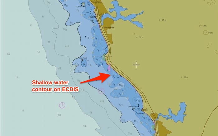
1.10.1 Shallow Contour setting
A contour is a line separating a minimum depth area. For example, a 10 meter contour will be a line that separates waters below and above 10 meters depths. The contours are in the value of 5, 10, 15, 20, 30 and so on.
Shallow contour value need to be used to tell ECDIS what is the value of shallow waters for our draft. This is the value of depth below which it is definite for the vessel to get aground.
The shallow contour value need to be equal to or more than the draft of the vessel.
Let us say the vessel’s draft is 9 meters and we enter the shallow contour value of 9 meter. The ECDIS will display 10meter contour line as the shallow contour. If 10meter contour is not available, it will take next contour as the shallow contour for the vessel.
The shallow contour lets the navigator know that between 0meter depth and the shallow contour, the area is not navigable at all.
Safety Contour setting
Safety contour is the contour line beyond which we can navigate without any water depth concern.
This is the depth that takes into account the Draft, required UKC, Squat, CATZOC, and the Dynamic and draft components. This calculated value will be the Safety contour.
The safety contour provides a visible boundary between “safe” and “unsafe” water with respect to depth, and is highlighted on the display to enable easy identification.
The Safety contour setting is made by the navigator after taking into account:
Ø Ship’s draught
Ø Under Keel clearance requirement (as per UKC Policy)
Ø Squat
Ø CATZOC
Ø Dynamic components:
· Tide allowance
· Dock water allowance (DWA) / Fresh water allowance (FWA)
· Wave height
Ø Draft components:
· Heel correction
· Rolling allowance
However, ECDIS will choose the next higher contour as the safety contour if this depth value is not available. If, for instance, the safety depth is 11 m and the safety contour is also set to 11 m the ECDIS will display the next available safety contour of the ENC in use. If the safety contours of the ENC are set in 5 meter the safety contour displayed on the chart will be the 15 m contour.
Safety Depth setting
Safety depth is the only depth setting on ECDIS.
Safety depth is the depth of the water we can safely navigate upon. It is the depth that satisfies the UKC policy.
In ECDIS we need to enter this minimum depth. It is same what was calculated in safety contour setting.
But the question is why do we need safety depth settings when we can navigate in waters above the safety contours? This is because of two straight forward reasons
Deep water contour
This is a relative term and Master is free to set what he believes could be deep water for him.
But there can be number of ways we can use the deep water contour setting.
For example, you can set the deep water contour to show the maximum anchoring depths where vessel can drop anchor. So if your vessel can anchor maximum 105 meters depth, you can set the deep water contour to 100 meters.
Or if you are about to do ballast water exchange, you can set the deep water contour to 200 meters. This way you can easily see just by the color on the ECDIS if you are in depths where ballast exchange can be done.
Colour display setting:

Safe channe l w i d th
1
T he safety parameters as required by the master’s orders must not be changed by the watch officer. Under no circumstances are these to be altered without the express order of the master. Should the safety parameters stipulated by the master in the passage plan be amended during the voyage on the master’s request, then this must be recorded in the deck log book.
1.11 Crossing the Safety Contour:
If the vessel does require to cross the safety contour, one of the below methods may be used after taking into account the hazards associated with each method, the prevailing conditions, vessel condition, the capabilities of the ECDIS equipment onboard and
Depth Accuracy 3
T y pical Survey
Characteristics 5
=0.50 + 1%d
Full area search undertaken. Significant seafloor features detected 4 and depths measured.
Controlled, systematic survey 6 high position and depth accuracy achieved using DGPS or a minimum three high quality lines of position (LOP) and a multi-beam, channel or mechanical sweep system.
= 1.00 + 2%d
Full area search undertaken. Significant seafloor features
Detected 4 and depths measured
Controlled, systematic survey 6 achieving position and depth accuracy less than ZOC A1 and using a modern survey echo-sounder 7 and a sonar or mechanical sweep system.
= 1.00 + 2%d
Full area search not achieved; uncharted features, hazardous to surface navigation are not expected but may exist.
Controlled, systematic survey achieving similar depth but lesser position accuracies than ZOC A2, using a modern survey echo-sounder 5, but no sonar or mechanical sweep system.
= 2.00 + 5%d
Full area search not achieved, depth anomalies may be expected.
Low accuracy survey or data collected on an opportunity basis such as soundings on passage.
Worse than ZOC C
Poor quality data or data that cannot be quality assessed due to lack of information.
Unassessed - The quality of the bathymetric data has yet to be assessed
Explanatory notes quoted in the table:
1. The allocation of a ZOC indicates that particular data meets minimum criteria for position and depth accuracy and seafloor coverage defined in this Table. ZOC categories reflect a charting standard and not just a hydrographic survey standard. Depth and position accuracies specified for each ZOC category refer to the errors of the final depicted soundings and include not only survey errors but also other errors introduced in the chart production process. [Note: the rest of footnote I does not apply to paper charts and is therefore omitted from S-4].
2. Position Accuracy of depicted soundings at 95% Cl (2.45 sigma) with respect to the given datum. It is the cumulative error and includes survey, transformation and digitizing errors etc. Position accuracy need not be rigorously computed for ZOCs B, C and D but may be estimated based on type of equipment, calibration regime, historical accuracy etc.
3. Depth accuracy of depicted soundings= a+ (bxd)/ I 00 at 95% Cl (2.00 sigma), where d =depth in meters at the critical depth. Depth accuracy need not be rigorously computed for ZOCs B, C and D but may be estimated based on type of equipment, calibration regime, historical accuracy etc.
4. Significant seafloor features are defined as those rising above depicted depths by more than: Depth Significant Feature a. <40m2 m b. >40 m I 0% depth A full sea floor search indicates that a systematic survey was conducted using detection systems, depth measurement systems, procedures, and trained personnel designed to detect and measure depths on significant seafloor features. Significant features are included on the chart as scale allows. It is impossible to guarantee that no significant feature could remain undetected, and significant features may have become present in the area since the time of the survey.
5. Typical Survey Characteristics- These descriptions should be seen as indicative examples only.
6. Controlled, systematic surveys (ZOC A I, A2 and B) - surveys comprising planned survey lines, on a geodetic datum that can be transformed to WGS 84.
7. Modern survey echo-sounder -a high precision single beam depth measuring equipment, generally including all survey echo-sounders designed post 1970.

ECDIS failure
Refer to the Ship Emergency Response Manual for ECDIS related contingencies also refer to Appendix 8 for Ship specific contingency plans
E CDIS Data
The value of an ECDIS is only as good as:
(a) The accuracy of the information it receives, and
(b) How the information ECDIS displays is interpreted and used.
Scale
Make sure that information from radar or other external sensors being displayed on the ECDIS is on the same scale as the electronic chart being displayed. Most ECDIS systems can adjust the scale of an additional layer of information which has been input in a different scale so as to match that of its ENC; if not, it should be able to alert the watchkeeper so that he can make the adjustment manually. This procedure is known as 'moving up'. Always make sure you know which scale your ECDIS is operating on, and be aware of additional input perhaps being in a different scale, such as 12 mile range, 24 mile range, 1:50,000, or coastal instead of ocean.
Accuracy
In confined waters the accuracy of chart data - whether paper charts, ENC or RNC data - may be less than that of the position fixing system in use. This may especially be the case when using differential GNSS.
Updates
Make sure you are using the latest ENC or RNC update. You should be able to interrogate the ECDIS to check when the electronic chart you are using was last updated and what information was added. You should also check as to whether there is a more recent update available.
Only CD’s from authorized suppliers must be used to safeguard against corruption of ECDIS due to virus or other data files.
Manufacturers suggest deleting all charts from the ECDIS before the base-DVD charts are copied onto the ECDIS to avoid data failure. The copying of the Base-DVD to the ECDIS can only be done one unit at a time to ensure that at least one ECDIS is in operational mode.
The IHO ENC / ECDIS performance test is to be carried out whenever the base-DVD charts were copied to the ECDIS units.
NOTE: If the Navtex and T&P notices are not automatically transferred to the ECDIS then the Officer on Watch need to enter the data manually into the ECDIS. All cancelled messages need to be manually removed by the responsible officer. Masters are to include this in their bridge self audits.
PASSAGE PLANNING
Using unofficial charts
Preparing the passage plan
The procedures for passage planning are given in Marine Manual Chapter 01.
During the passage planning process that you must check and confirm that all of the electronic charts loaded onto the ECDIS, and which are going to be needed during the voyage, are official.
Any sections of the passage plan for which official charts are not loaded, must be clearly identified. It should be noted alongside the appropriate waypoints where the unofficial chart will be in use, along with an instruction that an official paper chart must be the primary method of navigation during that stage of the voyage.
You can easily add or remove waypoints on a selected route. Most ECDIS will allow you to store up to
999 waypoints, and should enable you to make notes alongside each of them.
With the appropriate software programs and other necessary equipment, ECDIS can be programmed with information on vessel's status, performance and ability to perform manoeuvers. It can also take into account information on the cargo weight, the vessel's engine data, speed, rates of acceleration, stopping characteristics and turning circle. All these can be used to help plan and monitor the vessel's passage. Much of this information should already have been programmed into your ECDIS. Check it is still there and is still accurate.
Once you have completed your passage plan on the ECDIS you should save it to disk and name it with an appropriate title; you can then call it up again as the ship either clears the berth and gets underway or when you reach open seas. When completed, you must print out a paper hard copy of the plan and keep it as a back-up in case the ECDIS later develops a fault. This print-out should be signed by all the Navigating Officers after they have been familiarized with the passage plan.
Temporary and preliminary notices have not yet been fully integrated into ENC or RNC data by all National Hydrographic Offices. Caution must be exercised when navigating solely with ECDIS as some ENC or RNC data may not take account of temporary or preliminary notices.
The only guaranteed source for T&P information at present are Notices to Mariners (NM) issued by National Hydrographic Offices. The United Kingdom Hydrographic Office (UKHO) includes T&P notices within its ENC’s by including this information in its ‘Admiralty Information Overlay’. This tool allows the notices to be displayed as an overlay to the ENC in the Admiralty Vector Chart Service (AVCS),
The use of T&P NTM information is considered an essential part of keeping navigational charts up to date. Ships using ECDIS therefore have to take special caution while updating T&P NTM.
Depending on vessel’s route and ENCs used, it should be confirmed whether onboard ENCs include T&P NTM or not. If onboard ENCs do NOT include T&P NTM, manual means for correction of T&P NTM should be done through relevant NTM.
Navigational warnings transmitted by satellite communications (for example, SAT C telex), NAVTEX receiver and radio-broadcasted warnings are by nature more short term and urgent than temporary or preliminary notices. Navigators using ECDIS should be aware of the ability to plot new dangers on electronic charts through the use of the Marine Information Objects (MIO) capability. The purpose of the MIO is to highlight navigational warning information on the electronic chart.
Navigational warnings should be marked on the charts relevant to the voyage.
A p p r aisal and planning tips:
· Consider which electronic charts will be used for the passage, ENC or RNC data
· Check areas where RCDS mode will be operated, identify whether appropriate sets of paper charts are carried check local requirements of coastal states that may require carriage of additional publications or local charts
· Check that electronic charts have been updated to the most recent version and chart permit licences have been bought and being valid for the duration of the intended voyage.
· Route check previous passage plans after chart updating to ensure that any new dangers added don’t present a risk to the ship
· Modifications to the passage plan may be necessary to accommodate new chart features such as reporting schemes, traffic separation schemes (TSS), isolated dangers, etc.
· When planning new waypoints and courses, always use the largest scale possible so all features of the chart can be readily identified and risk assessed
· Ensure that the plan takes into account sufficient cross track error (XTE) to accommodate any deviations for collision avoidance or currents
· Ensure adequate values are inputted for safety contour and depth alarms
· Once the route has been planned, check the entire passage plan berth to berth on a 1:1 scale by manually scrolling along the track
· If the route has been planned in conjunction with paper charts, cross-check the distances between the paper chart and electronic passage plans to ensure consistency
· Check that tidal information is up to date and correct
· Check that the ETA has been updated
· Check that accurate draft details have been entered
· Squat details should be considered
· Make a back-up copy of the plan and save on a separate disk (usually USB stick)
· Most ECDIS units are provided with an automatic route safety check. If installed this must be used to verify the passage plan.
Safe planning
Always plan the route using both the ECDIS and its back-up system, and make sure the route is entered in both save the completed passage plan onto a disk, and also print out a paper copy make sure your ECDIS has received all the recent updates to keep its charts accurate. Use the largest scale electronic chart appropriate for all alarm indicators or for entering safety contours and prohibited areas. Remember, ENC alarms will operate automatically from the largest scale data, while data to trigger an alarm on an RNC has to be manually entered by the operator on the largest scale chart when entering waypoints on the preferred selected route into the ECDIS, also feed in a alternate route with alternate waypoints, specify a limit for deviation from the selected route, check if there are safety zones set up on the ECDIS, and whether they are still correct.
Route monitoring
ECDIS makes route monitoring very easy, but you must avoid relying entirely on it or radar as the only methods of safeguarding the vessel: it is important to always continue maintaining a regular look-out from the bridge. Always keep a navigation log on paper as well as the automatic ECDIS log. It is necessary to keep both the ECDIS and paper logs for at least one year.
The Master must specify at the outset of a voyage what standard information is needed to be on ready display on the ECDIS, such as chart orientation, range on display, safety zone and contour, he must also verify the same during route monitoring stage and verify that Watch keepers are aware of same.
Under special circumstances such as severe weather, if the Officer of the Watch wants additional information to be displayed for quick consultation, he can do so provided the display is set back to show standard information thereafter.
Adjusting a passage plan is easy as the voyage progresses. During route monitoring the ECDIS display will not only show the ship's position, but can also provide such information as the distance left or right of the intended track, time-to-run, distance-to-turn, position and time of 'wheel over', and past track history. Your ECDIS system should be able to keep a constant calculation of your passage, showing your ETA, required speed and elapsed time.
E xecution and monitoring tips:
• Check that the display has been set-up properly prior to sailing, otherwise important information may not be displayed
• Always operate ENC on the best scale possible to avoid crucial information being auto-filtered
and subsequently not being displayed
• Do not use ‘base display’ mode as this only displays the minimum amount of features and information
• Use ‘full display’ mode, but layers of information may need to be de-selected to avoid cluttering
the display with too much information
• Auto-filter or ‘SCAMIN’ may affect the display as it tends to remove information from the display if the best scale chart is not being used. Operators should know how to select the best scale chart to avoid the auto-filter feature removing information when using ENCs
• Ensure the GPS unit providing constant position fixing information to ECDIS has been updated with any relevant chart datum offset if the chart datum used in the raster chart is different from WGS (84). Failure to do so may result in positions being inaccurate
• Do not solely rely upon GPS position fixing when there are alternative position fixing facilities available. GPS is subject to a variety of different errors
• Traditional forms of position fixing should never be overlooked or replaced when using ECDIS;
these can include but are not limited to:
§ Visual bearings
§ Radar ranges and bearings using variable range markers (VRMs) and electronic bearing lines (EBL)
§ Transit bearings and clearing ranges
§ Running fixes
§ Fixing by a line of soundings
§ Horizontal sextant angles (HSAs)
§ Positions by celestial means (sextant)
• Make use of the Marine Information Objects (MIO) capability to plot electronically navigational warnings (e.g. NAVAREA warnings)
Safe monitoring
Whenever possible, have two electronic navigational systems in operation for establishing your vessel's position, set a generous time period for the ECDIS alarm to sound before your vessel crosses any safety boundary or begins to deviate from its planned route. When linked up with radar set a distance as per Master’s standing instructions for the ECDIS alarm to sound if another vessel approaches.
ECDIS usually offers the capability to overlay radar data onto the chart display. This may be selected targets or the full picture. According to the design, this option should be used frequently to verify the stabilization of the ECDIS image. Discrepancies between the radar image of a fixed object and its depiction as an electronic chart feature should be resolved by the “offset function” provided on the equipment.
The ECDIS must not be relied upon if the discrepancy between the radar display and the ECDIS
image persists, despite the use of the offset functions.
Target vectors, which are based on own ship’s speed through the water, will display incorrectly when overlaid on an electronic chart. Therefore when overlaying radar targets on an ECDIS display, the radar should be set to ‘ground-established’ (it follows that this should not be the radar used for collision avoidance).
Attention should be drawn to the following:
o Electronic Charts can be in vector or Raster chart format and the differences should be realized.
o The “look ahead” capability of raster charts is limited.
o When using raster charts, the automatic alarm features on the ECDIS system will not be triggered.
o If the equipment allows for radar targets to be overlaid onto the ECDIS output screen, it should
o be remembered; that the Radar will be set up to display targets allowing for ship’s log speed and not speed over the ground which the ECDIS will show.
The Master shall also ensure that navigation officers are aware of the potential dangers of over reliance on this equipment. The information from the ECDIS must not be over relied on as it is intended as an aid to navigation.
All on board involved in the navigation of the vessel must ensure the ECDIS must not be used as the primary means of navigation unless the vessel is equipped with two independent, certified ECDIS units. The means for primary navigation remains the largest scale paper charts appropriate to the navigation of the vessel which is being used to monitor the vessel’s passage and plot the vessel’s position at intervals specified in the passage plan.
Where information, such as the vessel’s position is obtained from ECDIS or equivalent, this must be cross referenced with an alternative and reliable source.
ECDIS provides instant monitoring of the vessel’s position in relation to the electronic Chart. As a cross check of this instant monitoring, during coastal and port passages Parallel Indexing (PI) should be used as a comparison and must be recorded.
Master must be informed in event of failure or problems with the ECDIS.
Precautions against Virus
It is identified that the ECDIS equipment which is connected to other systems with other Software and data transfer done via USB/CD can be infected by Virus Infection.
If ECDIS is fitted with Anti-Virus software then the ECDIS will automatically detect the Virus and if fitted with an alarm, same should trigger. However many Units in use do not have such functions.
The ECDIS if not fitted with an Internal Anti-Virus, it is prudent to ensure all Hardware, Eg ,USB Sticks and CD/DVD should be scanned prior every use for downloading chart correction or updation of charts before inserting into the ECDIS Unit.
These corrections received on the communication system should be transferred onto a stand-alone computer for ECDIS functions. The USB Sticks and CD/DVD should be labelled and kept separately and used only on the Stand alone computer and then connected to the ECDIS Unit for transferring data.
If the Correction is received through a broadband connection to the Communication Computer then it is essential for a Firewall to be present between the Communication Computer and the ECDIS Unit. In this case it is possible to download correction and updates automatically onto the ECDIS Unit.
Master must ensure strict adherence that the Stand Alone Computer, USB sticks and CD used for transferring data is not used for any other purpose. The Anti-Virus Protection is up to date in order to prevent any Malfunction of the ECDIS Unit.
Module 1
F a m il i arization with the basic functions of ECDIS as described in ECDIS Manual:
a) Power on/off and preparations
b) C a ution
c) ECDIS Data and presentation of ECDIS Data
1. Various Menu and Task bars
2. Setting date and Time
3. Own Ship’s setting and symbol
4. Display Panel
5. Adjusting the Brightness and sound volume
6. Changing the display color
7. Zooming in / Zooming out
8. Display Charts in Various Ways
9. Chart Information
10. Switching the scale
11. Shifting Chart
12. Numerical Inputs
13. Selecting the Motion/ Azimuth
14. Reading out information on the object
15. Marking and Highlighting
16. Chart editing/ Correction
17. Entering Objects
18. Manual Chart corrections
19. Chart updating
20. Backup arrangement requirements
21. Logbook and its setting
Module 2
Module 3
Module 4
1. Limitation of ECDIS
2. Risk of over reliance on ECDIS Data
3. Errors – Interpretation, or displayed data
4. Trouble shooting
• Theory of ECDIS;
• International regulations and requirements governing the use of ECDIS;
• Knowledge of Raster and Vector Charts;
• Capabilities and limitations of ECDIS equipment;
• Capabilities and limitations of ECS equipment;
• Practical knowledge of the various features of the ECDIS;
• Practical passage planning on the ECDIS;
• Practical route monitoring on the ECDIS;
The training process is to be monitored with the familiarisation checklist provided with Appendix 5 of this manual. The checklist is to be submitted to the office together with the training certificate provided in Appendix 5.
Licensing
An ENC license is a data file that permits an ECDIS to open and use ENC chart data for a fixed period of time. The ENC license contains specific data describing the chart data that it covers the user, the ECDIS system and the duration of its application.
An ENC license permits the ECDIS to retrieve the specific chart data set for which it applies, and incorporate this data into the SENC that the ECDIS displays. Without a license you will only see background charts.
S ubscription Period
The subscription period is defined as the 12 month period from the date on which the first chart is ordered and every 12 months thereafter. All charts included in the subscription, regardless of time of ordering, expire on the same date.
License Period
As a basic a 12 months subscription is required. Within this period new charts may be licensed for periods of 3 or 6 months, or until expiry date of your basic subscription. Due to limitations set by some Hydrographic Offices, the license period for some ENCs can only be set to 12 months.
Electronic Chart Correction
Keeping the ECDIS fully up to date should be a high priority for the bridge team and should be treated as equally important as normal paper chart corrections.
The Master must ensure that all charts, ENC’s or Raster, are operating under the latest updates from CD/ROM’s .In case the corrections are being received directly via the communication computer from the provider then these corrections should be received once per week and a Base DVD will be received quarterly. In the event of not receiving the weekly updates from the provider directly via communication computer or through CD/ROM, master must immediately contact the Technical Department and/or the Admiralty Supplier. It is important that the Master check the expiry date of all permits/licenses and to record them, to avoid unplanned and dangerous situations such as losing the chart’s display. Once the latest update CD is received on board, transferring and updating procedure should be carried out immediately as described in Operator’s Manual.
On Vessels equipped with full ECDIS (two fully independent ECDIS provided) the requirement for the reception of weekly NTM, including all corrections applicable to chart folios in use, must be met. If, for whatever reason, this requirement is not met, such as corrections are not received timely, or a technical failure to upload the corrections is experienced, the Master must immediately notify the Technical Superintendent and Purchaser.
In case regular electronic chart corrections are not provided for the ECDIS, the equipment must not be used for navigation at any time
ECDIS software creates a database from the ENC data called the system electronic navigational chart (SENC) and from this selects information for display. The ECDIS software meanwhile receives and processes serial data from navigational sensors and displays that textual and graphical information simultaneously with the SENC information. It is the SENC that is equivalent to up-to-date charts, as stated by the Performance Standards. As originally conceived, ECDIS was designed to use internationally standardized and officially produced vector data called the ENC (electronic navigational chart). Only when using ENC data can ECDIS create an SENC, and thereby function in the ECDIS mode.
Updates for ENC are installed into the ECDIS separate from the ENC data itself. For the mariner, this involves activating a special utility accompanying the ECDIS and following the on-screen prompts. Within this same utility, update content and update log files in textual form can be viewed. Once the ECDIS software itself is reactivated, the update information is accessed in conjunction with the ENC data and the SENC database is created.
ECDIS should store and display on demand a record of updates, including the time of application to the ECDIS database, known as the system electronic navigational chart (SENC). This record should include updates for each ENC until it is superseded by a new edition
Just as ENC and updates are transformed into the SENC, so too are other data types accessed and combined. The user has the option to add lines, objects, text and links to other files supported by application. Referred to in the Performance Standards as data added by the mariner, these notes function as layers on the displayed chart. The user can select all or parts of the layers for display to keep clutter to a minimum. The mariner’s own layers, however, must be called into the SENC from stored memory. As a practical matter, not only must the mariner take care to associate file names with actual content, such as with manually created chart corrections, but also must realize that the files themselves do not have the tamper-proof status that ENC and official updates have.
Within the SENC resides all the information available for the display. The Presentation Library rules such as Standard Display and Display Base define what levels of information from the SENC can be shown. An ENC updating profile is contained within the IHO S-57 Edition 3.0 specification. This enables the efficient addition, removal or replacement of any line, feature, object or area contained within the ENC dataset. Guidance on the means and process for ENC updating is provided in IHO S-52, Appendix 1. In terms of what is called for in the IMO Performance Standards, an ENC dataset being used in an ECDIS must also have an ENC updating service. This permits the ENC and the SENC to be corrected for the intended voyage, and thus achieves an important component of SOLAS compliance.
Accordingly, ECDIS must be capable of accepting official updates to the ENC data provided in conformity with IHO standard. Updated cells are stored in a file and transmitted by e-mail, floppy disk or CD-ROM, or satellite. For example, PRIMAR charts and updates are delivered on two CD’s: the Base CD contains the PRIMAR database at the time indicated on the label and the second CD contains the updates for those charts. But the update CD also contains new charts issued since the base CD was printed. Since the operator must acquire the files and then initiate the update functions of the ECDIS software, this form of updating is referred to as semi-automatic.
Generally, ECDIS will reject updates if the update issuing authority is different from the cell issuing authority. It will also reject corrupted update files and files with an incorrect extension. ECDIS checks that updates are applied in the right sequence. If one update is missing the next update is rejected. An update CD-ROM should contain all available updates for all S57 cells. Generally, ECDIS will automatically run all updates in the right order for all cells. For S-57 data, the content of updates in text form can be viewed from within the utility that permits the management of chart data. Generally it can only be run when ECDIS is terminated. ECDIS is also capable of showing or hiding S-57 updates on a given chart or cell. The update must first be installed via the chart utility. After restarting ECDIS, and after loading into the display the particular chart with the correction, the correction should be manually accepted. That enables the function in S-57 chart options to show or hide the symbol indicating the location of the correction.
British RCS Corrections
For the British RCS system, updates for all 2700 charts affected by Admiralty Notice to Mariners are compiled and placed on a weekly ARCS Update CD-ROM. Applying the corrections is only semi- automatic (not fully automatic), but it is also error-free, and each CD-ROM provides cumulative updates. The CD-ROM’s are available through chart agents.
NOAA Corrections
In the U.S., NOAA has contracted with Maptech, Inc. to provide updating of all NOS raster charts using information from the USCG, NIMA and the Canadian Hydrographic Service (CHS). Maptech uses a “patch technique” to update only those parts of a given chart identified as needing correction. The method compares the existing chart file and its corrected counterpart on a pixel-by-pixel basis. The software creates a “difference file” that is associated with the existing raster file to which it applies. This difference file is then compressed so that a typical patch contains only a few kilobytes of data. Ninety- nine percent are under 10kb. Typical downloads for a chart take 15 seconds to 5 minutes depending on modem speed.
The raster chart is updated as the patch file alters the pixels on the original chart. Update patches are available by download, and are cumulative for the all the charts packed on a given source folio CD. Further refinement will permit the separate storage of the RNC and update patches, so that as the patch is applied dynamically in real time, the user will be able to view the correction. The dynamic patching is similar to ENC updating in that the original chart data is not altered.
PMS
Recommendations. The Quarterly, Monthly and Weekly checks should include the below, however it is not restricted to the below items only and other type specific equipment requirements must be included in the PMS.
The Staff onboard must test ECDIS on backup power, check user chart function, ECDIS electronics log book, cell permit, tracker ball and keyboard, system safeguards such as Password protection are active and tested at least on monthly basis.
Ensure Antivirus is up-to-date and check must be done on all USBs and CDs used in the system. Weekly checks of chart (ENC, RNC and paper if carried) correction and other updates, connectivity of all equipment’s (channel view) and ship's position verification between GPS and ECDIS must be performed.
All alarms and indicators as per IMO A.830 (19).2 must be tested on weekly basis. UPS battery conditions must be checked on monthly basis.
The IHO ENC / ECDIS data presentation and performance tests are to be done on a quarterly basis whenever the latest base-DVD data was copied to the ECDIS, after an ECDIS failure, after technical services conducted and after the system was upgraded. The results are to be recorded in the PMS and the test report is to be submitted to the vessel’s superintendent. The superintendent must submit the test result to the IHO via their web interface at www.iho.int.
This is to certify that
Name: …………………………………………………………………………………………. Rank: ………………………………………………………………………………………….. Passport / CDC No: …………………………………………………………………………
S ignature of Trainer
S hip Stamp Date:
Note :
Original To be retained in the Officers personal Certificate File. Copy to be sent to Office by email.
| V essel | |
| O ffic e r name | |
| ECD IS Maker / Type | |
| D ate and time training commenced | |
| D ate and Time training completed | |
| N ame / Rank of officer providing the on-board training |
| 1 | INITIAL PREPARATION | Initials Trainee | Initials Trainer |
| 1.1 | Establish whether there are Bridge Instructions concerning the use of equipment and ensure that these are followed | ||
| 1.2 | Establish whether the equipment is a flag‐approved ECDIS. If not, paper charts must be used as the primary charting system | ||
| 1.3 | Identify the primary ECDIS equipment and the facilities for back‐up. If the back‐up is a second ECDIS of a different type to that of the primary installation, then Sections 2 to 6 of this familiarisation checklist must be repeated for both systems | ||
| 1.4 | Establish whether emergency charts are carried as a final level of back‐up. If so, determine their location and their suitability for the voyage. | ||
| 1.5 | Establish whether an emergency computer such as a laptop running ECS software is available. If so determine its whereabouts and how to switch on and access the ECS package. | ||
| 1.6 | Establish whether there is an on‐board approved familiarisation training package for the equipment, whether as computer based training, an inbuilt training mode or as a book or digital image of a book (eg. PDF file). Use this before completing the check list items here | ||
| 1.7 | Determine whether the user manuals for ECDIS and its back‐ up are located ‐ an electronic version of these may be available on each unit | ||
| 1.8 | Establish whether any passwords are needed for the operation of the system and, if so, obtain the details. Passwords for system settings should remain in the possession of the master to ensure consistency. | ||
| 1.9 | Determine where Base and Update CDs are stored on the ship | ||
| 1.10 | Determine the procedures to obtain additional chart permits | ||
| 1 | INITIAL PREPARATION | Initials Trainee | Initials Trainer |
| 1.11 | Determine and understand the position‐fix systems that feed the ECDIS. Determine the method of switching between sources, such as primary and secondary position‐fix systems | ||
| 1.12 | Determine what other systems feed into the ECDIS, such as radar (tracked targets and/or raw), AIS, water speed logs, echo sounders, etc. For each, establish the reference framework, eg. ground ‐, water‐ or ship‐stabilised (relative) |
| 2 | B A S IC OPERATION | Initials Trainee | Initials Trainer |
| 2.1 | Determine how to switch the ECDIS on and off | ||
| 2.2 | Establish the function(s), position and general operation of the physical controls and switches , including cursor control, and the access and selection of menu items | ||
| 2.3 | Understand how to access the main menu and select menu options | ||
| 2.4 | Determine the methods for setting day/night viewing modes, brightness, contrast and colour correction (if available) | ||
| 2.5 | Determine how to switch between traditional and simplified symbology | ||
| 2.6 | Determine how to put equipment in route‐monitoring mode and route‐planning mode | ||
| 2.7 | Determine the methods for scrolling and zooming charts, including determining the current scale of displayed charts and setting the display to a particular scale | ||
| 2.8 | Determine how to select the Display Base and Standard Display | ||
| 2.9 | Determine how to add display other information from ENCs, including the display of All Other Information | ||
| 2.10 | Determine how to check that information concerning own ship, such as dimensions are correct | ||
| 2.11 | Determine how to select the safety contour and safety depth | ||
| 2.12 | Determine how to select two‐ or four‐colour contour mode | ||
| 2.13 | Determine how to select deep and shallow area display options | ||
| 2.14 | Determine how to set all other parameters condering the safety domain | ||
| 2.15 | Establish how alarms and other alerts are given by the ECDIS and the procedure needed to acknowledge them |
| 3 | CHARTS | Initials Trainee | Initials Trainer |
| 3.1 | Determine how to access the chart directory and to identify whether charts are ENCs, RNCs or private data | ||
| 3.2 | Determine how to select a chart for display on the screen | ||
| 3.3 | Determine how to load new chart licence keys | ||
| 3.4 | Determine how to load base data | ||
| 3.5 | Determine how to check the update status of loaded charts | ||
| 3.6 | Determine how to update charts using the normal cumulative update procedures | ||
| 3.7 | If applicable, determine how to apply non‐cumulative or electronically‐transmitted updates | ||
| 3.8 | Determine how to apply manual updates |
| 4 | N A VIGATION TOOLS AND FUNCTIONS | Initials Trainee | Initials Trainer |
| 4.1 | Determine how to display the legend of general information | ||
| 4.2 | Determine how to select information about an object (Pick report) | ||
| 4.3 | Determine how Zone of Confidence (CATZOC) information can be displayed | ||
| 4.4 | Determine how to access the Presentation Library | ||
| 4.5 | Determine what Marine Information Overlays are available and how to access them. (Radar and AIS covered in Section 6 below) | ||
| 4.6 | Determine the 'single operator action' needed to remove MIOs from the display | ||
| 4.7 | Determine the 'single operator action' needed to set the Standard Display setting | ||
| 4.8 | Determine how to view, add, edit and delete Mariners' Notes | ||
| 4.9 | Determine how to access all navigational elements and parameters, such as past track, vectors, position lines, etc | ||
| 4.10 | Establish the facilities provided for the measurement of range and bearing (eg EBLs and VRMs) and determine their use | ||
| 4.11 | Determine the method(s) used for inserting Parallel Index lines | ||
| 4.12 | Determine what other navigational tools are available and how to access them | ||
| 4.13 | Determine how to switch to using the back‐up system | ||
| 5 | ROUTE PLANNING | Initials Trainee | Initials Trainer |
| 5.1 | Determine how to load existing routes and enable for editing | ||
| 5.2 | Determine how to initiate a new route plan | ||
| 5.3 | Determine how to initiate and plan alternate routes | ||
| 5.4 | Determine how to save route plans | ||
| 5.5 | Determine how to add, delete and adjust graphically the position of waypoints | ||
| 5.6 | Determine how to add, edit and delete critical points | ||
| 5.7 | Determine how to display time varying objects relevant for the timing of the planned voyage | ||
| 5.8 | Establish all the features available for planning routes, such as of straight and curved segments and inserting pilotage aids | ||
| 5.9 | Determine the ship's procedures for displaying MSI, T&P Notices and other relevant notes into the voyage plan | ||
| 5.10 | Determine how to use the facilities for checking the planned route | ||
| 5.11 | Determine how to load the planned route and alternatives into the back‐up system |
| 6 | ROUTE MONITORING | Initials Trainee | Initials Trainer |
| 6.1 | Determine how to load a pre‐planned route | ||
| 6.2 | Determine how to select the primary or an alternate route and how to distinguish between them on the display | ||
| 6.3 | Determine the single operator action that selects the charted display of own ship's position | ||
| 6.4 | Determine the available display orientation modes and how to switch between them (eg. North Up, Head Up, Course Up) | ||
| 6.5 | Determine the available display motion modes and how to select them and change the parameters, such as the position of own ship on the display when Relative Motion is selected | ||
| 6.6 | If radar or AIS targets can be displayed on the ECDIS, determine what target vector modes are available and how to switch between and differentiate them | ||
| 6.7 | Determine how to create time labels along the ship's track | ||
| 6.8 | Establish familiarity with the Route Monitoring display, including the display of position, heading, course, speed and time | ||
| 6 | ROUTE MONITORING | Initials Trainee | Initials Trainer |
| 6.9 | Determine how to set the length of own ship's vector and intermediate time marks | ||
| 6.10 | Determine how to display radar and AIS MIOs, if available | ||
| 6.11 | Determine how to use the ECDIS as the input to a track‐ keeping autopilot. This will also need reference to the autopilot handbook | ||
| 6.12 | Determine how to input LOP to form the reference for an estimated position | ||
| 6.13 | Determine how to configure the ECDIS to use this reference (6.8) for subsequent Eps | ||
| 6.14 | Determine how to use the review facilities of the voyage recorder (not essential knowledge prior to sailing) |
Once the watch officer has completed the familiarization and the familiarization is verified by the master Appendix V of the Company ECDIS manual is to be completed and the signed and scanned copy of the Appendix to be sent to the responsible crewing staff in the office. Only when all items of the above checklist are fully understood by the officer can he stand a bridge watch alone.
Signature Officer being Trained
Signature of Officer providing training
Signature of the Master
This is attached separately
This is attached separately
Electronic Chart Display and Information System
(ECDIS) Manual
Последнее изменение этой страницы: 2019-03-22; Просмотров: 549; Нарушение авторского права страницы