|
Архитектура Аудит Военная наука Иностранные языки Медицина Металлургия Метрология Образование Политология Производство Психология Стандартизация Технологии |
|
|
Архитектура Аудит Военная наука Иностранные языки Медицина Металлургия Метрология Образование Политология Производство Психология Стандартизация Технологии |
Тема 4. Very High Frequency (VHF) communication.Стр 1 из 8Следующая ⇒
Тема 4. Very High Frequency (VHF) communication. УКВ-радиостанции. Цель лекции: Изучение УКВ-радиостанций. Вопросы лекции: 4.1. Назначение; 4.2. УКВ радиостанция «Баклан-20»; 4.3. Very High Frequency (VHF) communication; 4.4. VHF communications В737 и А320; 4.5. Static dischargers. Назначение. УКВ радиостанции (радиостанции СВЧ-связи) предназначены для ведения ближней телефонной симплексной радиосвязи экипажа самолета с наземными диспетчерскими службами УВД, а также для связи между экипажами самолетов, находящихся в воздухе. Они работает в диапазоне 118-137, 975 МГц, шаг частоты настройки 25/8, 33 кГц. Так как это основная связная система, на ЛА устанавливают, как правило, 2 или даже 3 комплекта аппаратуры. Соответственно имеется две антенны, одна – верхнего расположения (на нее работает основной комплект), другая – нижнего расположения (на нее работает второй комплект). VHF communications В 737 и А 320. Подробно рассматривается соответственно в [3] и [5] рекомендуемой литературы. General The very high frequency (VHF) communication system supplies communication over line-of-sight distances. It gives communication between airplanes or between ground stations and airplanes. Abbreviations and Acronyms · ACARS - aircraft communications addressing and reporting system · ACP - audio control panel · AM - amplitude modulation · ARINC - Aeronautical Radio Incorporated · BITE - built-in test equipment · comm - communication · EEC - electronic equipment compartment · FDAU - flight data acquisition unit · FDR - flight data recorder · freq - frequency · I/C - interphone communication · LCD - liquid crystal display · LED - light emitting diode · LRU - line replaceable unit · mic - microphone · MSEC - milli-second · PSEU - proximity switch electronics unit · PTT - push-to-talk · RCP - radio communication panel · REU - remote electronics unit · RF - radio frequency · R/T - receive/transmit · SELCAL - selective calling · sql - squelch · SSB - single side band · SSFDR - solid state flight data recorder · VHF - very high frequency · VSWR - voltage standing wave ratio · xmit - transmit
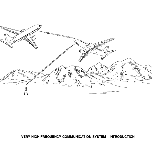
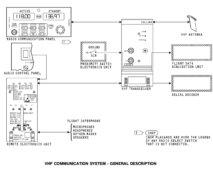
General The VHF communication system supplies the flight crew with voice and data line-of-sight communication. The VHF communication system can be used to communicate between airplanes and between airplanes and ground stations. The VHF communication radio is tunable in the frequency range of 118.000 MHz to 136.975 MHz. The VHF radio is used to transmit and receive voice and data communication. System Components The VHF communication system has these components: · Radio communication panel · VHF transceiver · VHF antenna.
The RCP supplies selected frequency signals to tune the VHF transceivers. You can use the RCP to select the frequency of any VHF communication radio. The VHF transceiver transmit circuits modulate an RF carrier signal with voice or data audio. The receive circuits demodulate the received RF carrier signal to detect the audio from the RF carrier. The detected audio is used by the flight crew and other airplane systems. The VHF antenna transmits and receives RF signals. External Interface The VHF communication system connects with these components/systems:
· Remote electronics unit (REU) · Proximity switch electronic unit (PSEU) выкл-ль сближения с землей · SELCAL decoder unit · Flight data acquisition unit (FDAU). Приобретение
System Operation The control panel sends selected frequency signals to the transceiver. The audio control panel sends radio select signals and receive volume control to the REU. During transmit, microphone audio and PTT signals go to the VHF transceiver through the REU. The transceiver uses the microphone audio to modulate an RF carrier signal made in the transceiver. The transceiver sends the modulated RF signal to the antenna for transmission to other airplanes and ground stations. During transmit, the flight data acquisition unit receives a PTT signal from the transceiver. The flight data acquisition unit uses the PTT for key event marking to record the transmit event. During the receive operation, the antenna receives a modulated RF signal and sends it to the transceiver. The transceiver demodulates or removes the audio information from the RF carrier. The received audio goes from the VHF transceiver through the REU to the flight interphone speakers and headsets. The SELCAL decoder unit receives audio from the VHF transceiver. The SELCAL decoder unit monitors the audio for SELCAL calls that come from the ground station. The VHF transceiver receives an air/ground discrete from the PSEU (proximity switch electronics unit). The VHF transceiver uses the discrete to calculate flight legs for internal fault memory.
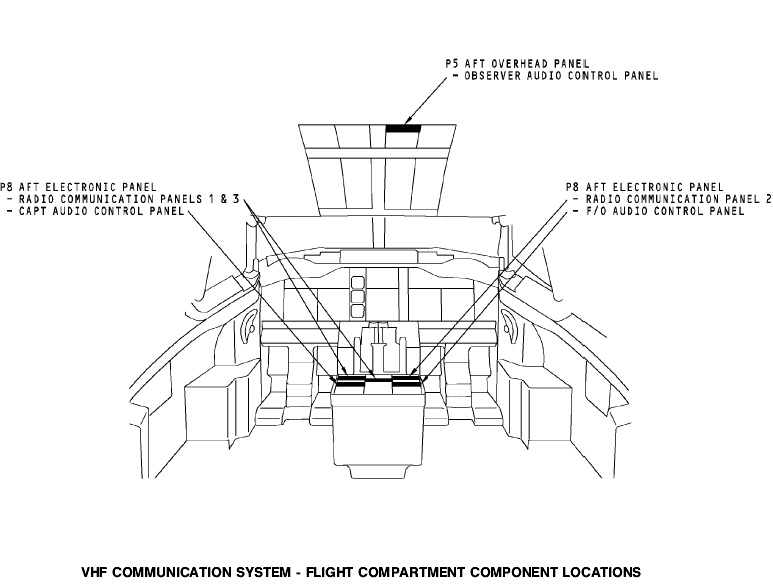
Flight Compartment
The radio communication panels are on the P8 aft electronic panel. The audio control panels (ACPs) are part of the flight interphone system. The ACPs have an interface with the VHF communication system through the REU. The captain and first officer ACPs are on the P8 aft electronics panel. The first observer ACP is on the P5 aft overhead panel.
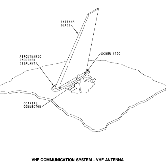
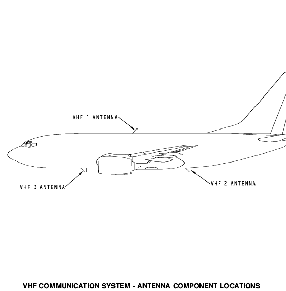
General The VHF antennas are on the top and the bottom of the airplane fuselage on the centerline.
Power
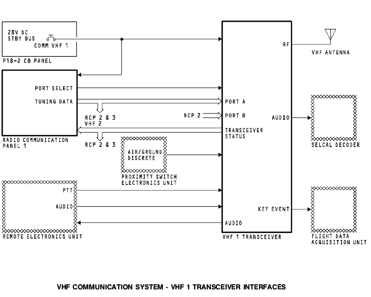
The 28v dc standby bus supplies power to the VHF 1 transceiver and radio communication panel (RCP) 1. VHF 1 Transceiver The VHF 1 transceiver has an interface with these components: · RCP 1, 2, and 3 · VHF antenna · Proximity switch electronics unit · Remote electronics unit · SELCAL decoder unit · Flight data acquisition.
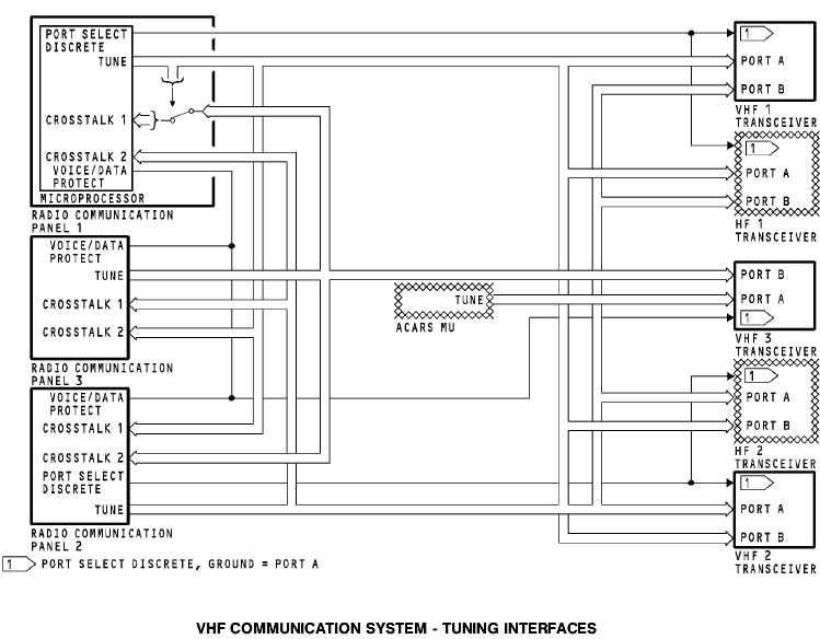
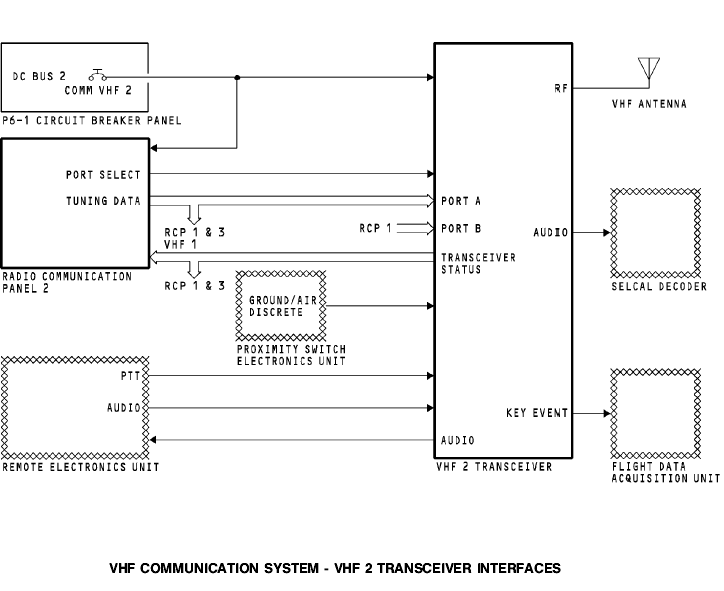
Radio Communication Panel RCP 1 supplies frequency information to the VHF 1 transceiver on an ARINC 429 bus to port A. RCP 2 supplies frequency information to the VHF 1 transceiver on an ARINC 429 bus to port B. RCP 3 can supply frequency data to the VHF 1 transceiver through RCP 1 or 2. For more information about tuning interfaces, see VHF Communication System - Tuning Interfaces. The VHF transceiver supplies the status of the transceiver to the RCPs. VHF Antenna The VHF antenna receives an RF signal from the VHF transceiver and transmits the RF signal to other airplane and ground VHF communication systems. The antenna also receives incoming RF signals and sends the RF signals to the VHF transceiver. The transceiver demodulates or detects the audio from the RF carrier signal. External Interfaces The VHF 1 transceiver has an interface with components from other airplane systems. The proximity switch electronic unit sends a ground signal to increase the flight leg count to track fault history. Увеличение расширение The remote electronics unit sends flight crew microphone (mic) audio to the transceiver to be transmitted. It also sends a PTT to start the transceiver transmit mode. The transceiver sends side tone and received audio to the REU for the flight interphone system. The transceiver sends received audio to the SELCAL decoder. The SELCAL decoder isolates the SELCAL code from voice audio. The flight data acquisition unit receives a PTT from the transceiver for key event marking. Power The dc bus 2 supplies 28v dc power to the VHF 2 transceiver and radio communication panel (RCP) 2. VHF 2 Transceiver The VHF 2 transceiver has an interface with these components: · RCP 1, 2, and 3 · VHF antenna · Proximity switch electronics unit · Remote electronics unit · SELCAL decoder unit · Flight data acquisition.
Radio Communication Panel RCP 2 supplies frequency information to the VHF 2 transceiver on an ARINC 429 bus to port A. RCP 1 supplies frequency information to the VHF 2 transceiver on an ARINC 429 bus to port B. RCP 3 can supply frequency data to VHF 2 transceiver through RCP 1 or 2. For more information on tuning interfaces, see VHF Communication System - Tuning Interfaces. The VHF transceiver supplies the status of the transceiver to the RCPs.
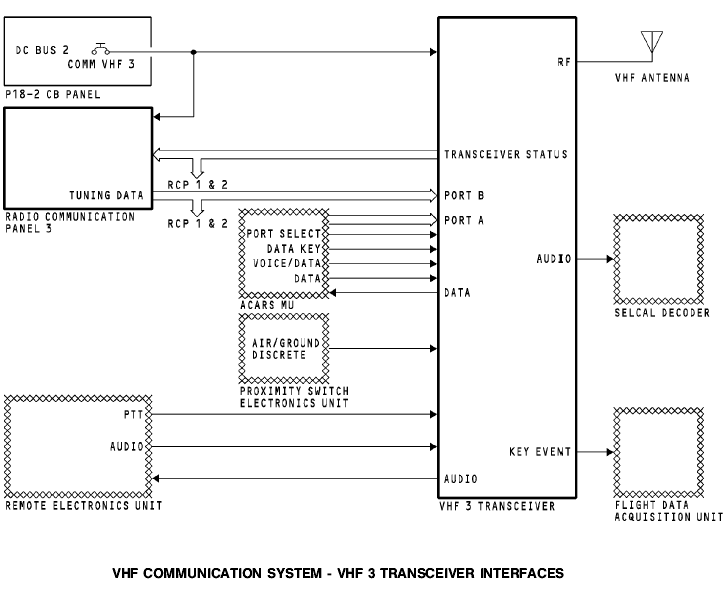
VHF Antenna The VHF antenna receives an RF signal from the VHF transceiver and transmits the RF signal to other airplane and ground VHF communication systems. The antenna also receives incoming RF signals and sends the RF signals to the VHF transceiver. The transceiver demodulates or detects the audio from the RF carrier signal. External Interfaces The VHF 2 transceiver has an interface with components from other airplane systems. The proximity switch electronic unit sends a ground signal to increase the flight leg count to track fault history. The remote electronics unit sends flight crew audio to the transceiver to be transmitted. It also sends a PTT start the transceiver transmit mode. The transceiver sends side tone and received audio to the REU for the flight interphone system. The transceiver sends received audio to the SELCAL decoder. The SELCAL decoder isolates the SELCAL code from voice audio. The flight data acquisition unit receives a PTT from the transceiver for key event marking. Power The DC bus 2 supplies 28v dc power to the VHF 3 transceiver and radio communication panel (RCP) 3. VHF 3 Transceiver The VHF 3 transceiver has an interface with these components: · RCP 1, 2, and 3 · VHF antenna · Proximity switch electronics unit · Remote electronics unit · SELCAL decoder unit · ACARS management unit · Flight data acquisition unit.
Radio Communication Panel RCP 3 supplies frequency information to the VHF 3 transceiver on an ARINC 429 bus to port B. The ACARS management unit (MU) sends tuning information to VHF 3 transceiver on an ARINC 429 bus to port A. For more information on tuning interfaces see VHF Communication System - Tuning Interfaces. The VHF transceiver supplies the status of the transceiver to the RCPs. VHF Antenna The VHF antenna receives an RF signal from the VHF transceiver and transmits the RF signal to other airplane and ground VHF communication systems. The antenna also receives RF signals and sends the RF signals to the VHF transceiver. The transceiver demodulates or detects the audio from the RF carrier signal. External Interfaces The VHF 3 transceiver has an interface with components from other airplane systems. The proximity switch electronic unit sends a ground signal to increase the flight leg count to track fault history. The remote electronics unit sends flight crew audio to the transceiver to be transmitted. It also sends a PTT to start the transceivers transmit mode. The transceiver sends received audio to the REU for the flight interphone system. The transceiver sends received audio to the SELCAL decoder. The SELCAL decoder isolates the SELCAL code from voice audio. The ACARS management unit sends these discrete signals to the VHF 3 transceiver: · Port select discrete to set the tuning data source · Data key to give a PTT signal · Voice/data to set transceiver voice or data mode. The ACARS management unit sends data audio to the VHF 3 transceiver to be transmitted to the ground station. The VHF 3 transceiver sends received data audio to the ACARS management unit. The flight data acquisition unit receives a PTT from the transceiver for key event marking.
The VHF communication system uses data buses to share tuning information between the radio communication panels (RCPs) and the communication transceivers. Tuning Bus Each RCP has one ARINC 429 output bus. The RCPs send tuning data to the communication transceivers. Any RCP can tune any transceiver. Each RCP sends tuning data and status to the other radio communication panels. This keeps the tuning data synchronized and lets any RCP tune any transceiver. The RCP keeps the tuning data in memory. Usually, the RCP uses the tuning data from its memory to send on the output bus. The RCP can connect the CROSSTALK 1 bus directly to the output bus. This occurs for these RCP conditions: · RCP does not have power · RCP is OFF · RCP is failed. Port Select Discrete RCP 1 and 2 send the port select discretes to the transceivers. The ACARS MU sends a port select discrete to the VHF 3 transceiver.
The RCPs send the voice/data protect discrete to the VHF 3 transceiver. This discrete selects either the ACARS management unit or the RCPs to tune the VHF 3 transceiver. Each transceiver has two tuning data input ports, port A and port B. The transceiver uses the port select discrete to select the input port. A grounded port select discrete causes the transceiver to use port A. An open port select discrete causes the transceiver to use port B. Training Information Point These are the RCP VHF radio selections when the airplane receives power and there are no RCP faults: · RCP 1 - VHF 1 · RCP 3 - VHF 3 · RCP 2 - VHF 2.
If RCP 1 fails, you can tune the VHF 1 transceiver with RCP 2 or 3. RCP 1 port select discrete changes from ground to open, and RCP 2 sends tuning data to input port B. RCP 3 sends tuning data on CROSSTALK 2 bus which connects to RCP 2. RCP 2 sends this tuning data to the VHF 1 transceiver on the output TUNE bus. If RCP 2 fails, you can tune the VHF 2 transceiver with RCP 1 or 3. RCP 2 port select discrete changes from ground to open, and RCP 1 sends tuning data to input port B. RCP 3 sends tuning data on CROSSTALK 1 bus which connects to RCP 1. RCP 1 sends this tuning data to the VHF 2 transceiver on the output TUNE bus. If RCP 3 fails, you can tune the VHF 3 transceiver with RCP 1 or 2. RCP 1 sends tuning data to RCP 2 on CROSSTALK 1 bus. RCP 2 puts RCP 1 tuning data on the output TUNE bus. RCP 2 output TUNE bus is connected to RCP 3 CROSSTALK 1 bus. The bus relay in RCP 3 is closed. The tuning data connects directly to the output TUNE bus and goes to the VHF 3 transceiver. RCP 2 tuning data goes to the RCP 3 CROSSTALK 1 bus and to VHF 3 transceiver on the output TUNE bus.
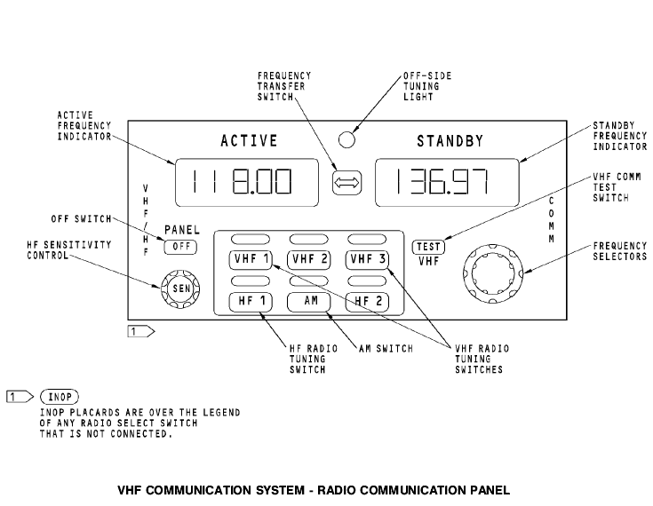
General The radio communication panel (RCP) provides these functions: · VHF and HF radio selection · Active/standby frequency selection · HF sensitivity control · Test initiation to the VHF transceiver · Mode selection to the HF transceiver · Off switch.
Controls and Indicators Any radio communication panel can control any transceiver. Push the radio tuning switch to select the transceiver for that radio communication panel. The light above the switch comes on. Each radio communication panel can tune only one transceiver at a time. неглавный When you select an off-side radio, two off-side tuning lights come on. One light is on the radio communication panel that you use to make the selection. This is the off-side radio. The other light is on radio communication panel of the radio you select. This is the on-side radio. Set the frequency in the standby frequency indicator. Turn the frequency selectors to set the frequency. The first digit is always цифра символ -- 1. The outer knob sets the second two digits (10 MHz and 1MHz) in 1 MHz increments. The inner knob sets the fourth, fifth, and sixth digits (100 kHz, 10 kHz, and 1 kHz) in 25 kHz increments. Внешний наружный ручка головка кнопка шаг приращение
Push the frequency transfer switch to change the active and standby frequencies. The HF SENS control sets the RF sensitivity level of the HF transceiver. Rotate the control to adjust the sensitivity of the HF transceiver. The inactive frequency indicator shows a value between 0 and 99. Maximum sensitivity is 99. Minimum sensitivity is 0. After a delay, the inactive frequency indicator shows the inactive frequency again. The VHF communication test switch starts a confidence check of the VHF transceiver. Push the VHF communication test switch to stop the squelch in the VHF transceiver. You hear static when you push the switch. Помехи сх. Бесшумной настройки Push the OFF switch to stop the operation of the radio communication panel. The switch shows white when it is off. BITE The radio communication panel continuously does a self-test. The frequency indicators show PANEL FAIL when there is an internal failure of the radio communication panel.
Purpose The purpose of the VHF transceiver is to transmit and receive information. Physical Description The transceiver is a solid state device. It has these components: устройство схема · Power supply · Frequency synthesizer · Receiver · Modulator · Transmitter · Microprocessor.
Functional Description The transceiver has these properties: · 118.000 to 136.975 MHz frequency range · Voice or data operation · 25 watts output power · Built-in fault detection and memory.
Power The transceiver operates with +27.5v dc. Controls, Indicators, and BITE Push the TEST switch to start a system self-test. This includes these tests: · Transceiver self-test · Input serial tuning word test последовательный периодический · Antenna VSWR test.
The front panel LEDs show the results of the VHF system selftest. These are the front panel LEDs: · LRU · CONTROL · ANTENNA.
The LRU LED shows a failure of the transceiver. The CONTROL LED shows a failure of the ARINC 429 input. The ANTENNA LED shows a failure of the antenna. All LEDs come on red for three seconds. Then the LRU LED changes to green and the other LEDs stay red for three seconds. Then the LRU LED comes on green for 30 seconds and the CONTROL and ANTENNA LEDs go off. The LRU LED comes on red after the self-test if there is a transceiver failure.
General Description The VHF antenna receives and transmits RF signals in the VHF frequency range. The antenna attaches with 10 screws. There is an aerodynamic smoother around the antenna base. This aerodynamic smoother is a sealant. An o-ring seals the coaxial connector. NOTE: For the top antenna, the cable can fall through the hole. Уплотнитель гермет - ки закрывать When you remove the top antenna, make sure you attach the cable to something to prevent this.
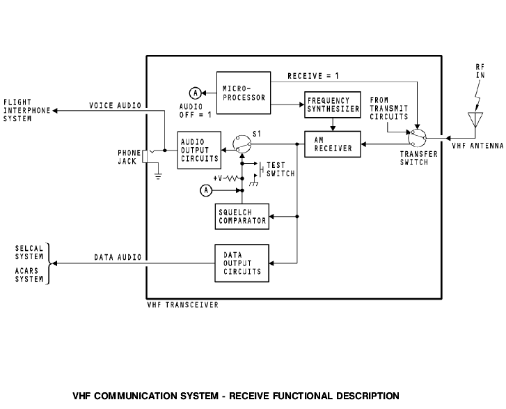
Receive Operation The VHF antenna receives RF signals and sends them to the VHF communication transceiver through the coaxial cable. The transceiver sends the RF signal through the receive circuits and then sends the audio to the flight interphone system. The transceiver also sends data to the selective calling (SELCAL) decoder.
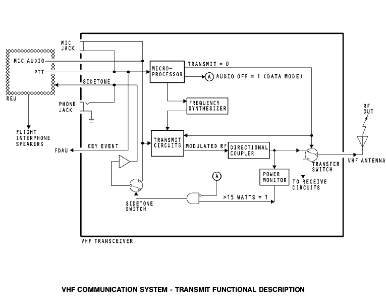
The VHF 3 transceiver sends data to the aircraft communications addressing and reporting system (ACARS) management unit. The microprocessor sends the receive frequency to the frequency synthesizer. The frequency synthesizer sets the frequency of the AM receiver. The microprocessor also sends a logic 1 to the transfer switch when the transceiver is in the receive mode. This closes the transfer switch and sends the RF signal from the antenna to the AM receiver. The AM receiver demodulates the RF input and detects the audio signal. The audio output from the AM receiver goes to these circuits: · Data output circuits · Switch S1 · Squelch comparator.
The audio output circuits send the audio signal to the flight interphone system and to the headphone jack. Do a test of the receive audio circuits with the TEST push button. Push the TEST push button to close switch S1 and send the receive audio to the audio output circuits. This lets the operator hear background noise not normally heard. порог The squelch comparator circuit compares the detected audio with a threshold value. If the level of the detected audio is larger than the threshold, the squelch circuits sends a ground to switch S1. Switch S1 closes and sends the audio to the audio output circuits. For the VHF 3 transceiver, the microprocessor changes the audio off signal to a logic 1 when the transceiver is in the data mode. This causes switch S1 to open and disable the audio output and the squelch comparator.
Transmit Operation The VHF tranceiver receives audio from the remote electronics unit (REU). The transceiver sends the signals through the transmit circuits and then to the antenna for transmission. During transmission, the microprocessor receives a push-totalk (PTT) signal from the REU. This causes the microprocessor to send a logic 0 to the transfer switch. The transfer switch connects the output of the transmit circuits to the VHF antenna. Mic audio from the REU goes to the transmit circuits in the transceiver. The transmit circuits modulate the RF carrier with the mic audio. This makes an amplitude modulated RF signal. The signal goes to the directional coupler and transfer switch. The RF signal goes through the transfer switch and to the antenna. The antenna transmits the RF signal. The RF output from the directional coupler also goes to the power monitor. The power monitor sends a logic 1 when the output power is larger than 15 watts. The side tone switch closes when the output power is larger than 15 watts and the transceiver is in the voice mode. The microphone audio goes through the REU to the flight interphone speakers.
For the VHF 3 transceiver, the microprocessor changes the audio off signal to a logic 1 when the transceiver is in the data mode. This sends a logic 0 to the sidetone switch and turns off the sidetone audio.
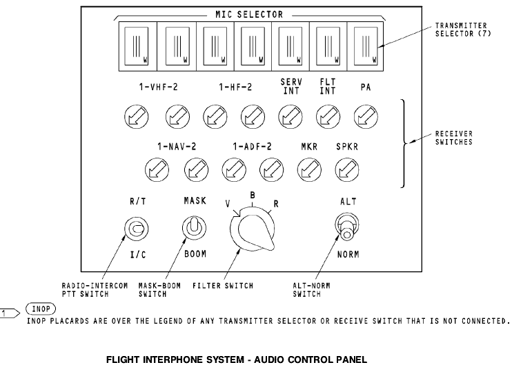
General You use these components to operate the VHF radio: · Microphone or headset · Control wheel mic switch · Radio communication panel (RCP) · Remote mic switch · Audio control panel.
Receive Operation
You use the radio communication panel and the audio control panel to receive transmissions on the VHF radio. On the audio control panel, push the receiver volume control for the VHF radio. Turn the control to adjust the volume from the VHF radio. You hear audio on the headset and the flight interphone speakers. To hear sound from the flight interphone speakers, push the speaker (SPKR) volume control to turn on the speaker. Turn the control to adjust the volume of sound from the speaker. В начале When you apply power to the airplane, the radio communication panels (RCPs) are on. Initially, RCP 1 tunes VHF 1 and RCP 2 tunes VHF 2. Push the VHF microphone selector switch for the VHF radio you want to use. A light above the switch comes on to show which radio the panel controls. When you push the audio control panel microphone selector switch, the VHF receiver volume control is automatically selected. The frequency indicators show VHF radio frequencies. The VHF transceiver tunes to the frequency in the active frequency indicator. Use the frequency selectors to tune the radio to a new frequency. The standby frequency display shows the new frequency.
When you are sure the frequency is correct, push the frequency transfer switch. The active frequency indicator shows the new frequency. The VHF radio uses the new frequency. Listen to the audio from the VHF radio on the speaker or headset. Adjust the volume control switches on the audio control panel for a comfortable sound level.
Transmit Operation
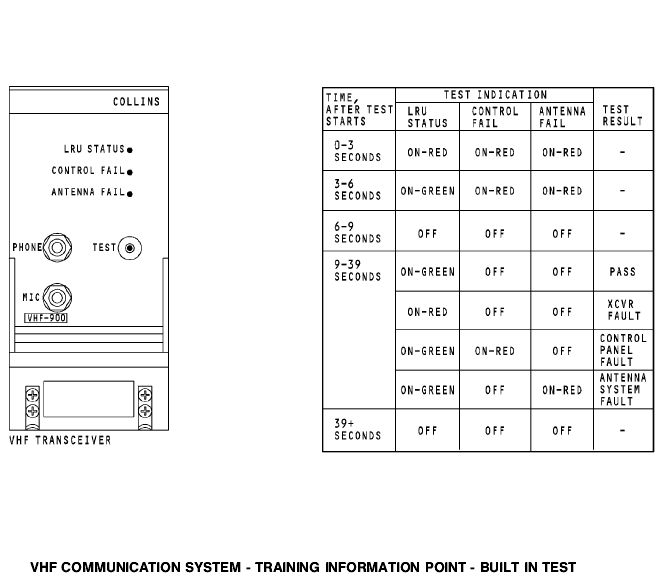
Make sure the active frequency indicator shows the frequency you want to transmit. Make sure the frequency you select is a valid transmit frequency. Push the microphone selector switch on the audio control panel for the VHF radio. Listen for transmissions on the frequency you selected. When the frequency is clear and you want to transmit a message, key the mic and speak into it. You hear sidetone in the headphone and muted sidetone from the speaker. The flight interphone system mutes the sidetone to the speaker when you use the boom mic or the hand mic. Приглушать звук General The VHF transceiver has built-in test equipment (BITE). You start the test on the front of the VHF transceiver. When you start the test, the built-in test equipment examines the input from the control panel or ACARS management unit, the internal circuits and processors of the transceiver, and the output to the antenna.
Test Operation When you push the TEST switch, the transceiver does these checks: · Monitors the power supply · Does a test of the memory devices устройство памяти · Does a test of the input from the control panel or the ACARS management unit · Does a test of the frequency synthesizer · Keys the transmitter for 100 ms at 128.475 MHz and does a test of the modulation, power and VSWR (voltage standing wave ratio) · Does a test of the receiver automatic-gain-control and squelch operation. Test Indications Push the TEST switch to start the test. The LRU STATUS, CONTROL FAIL, and ANTENNA FAIL indicators show red for three seconds. Then, the LRU STATUS indicator shows green and the other indicators show red for three more seconds. Then, all indicators go off for three seconds. Then, the transceiver shows the result of the test for 30 seconds. If the LRU STATUS indicator is green and the CONTROL FAIL and ANTENNA FAIL indicators are not on, then the test result is good. If an indicator is red, then there is a failure. The red LRU STATUS indicator comes on if there is a failure of the VHF transceiver. The red CONTROL FAIL indicator comes on if there is a failure of the signal from the control panel or the ACARS management unit. The red ANTENNA FAIL comes on if there is a failure of the antenna or the wiring between the transceiver and the antenna.
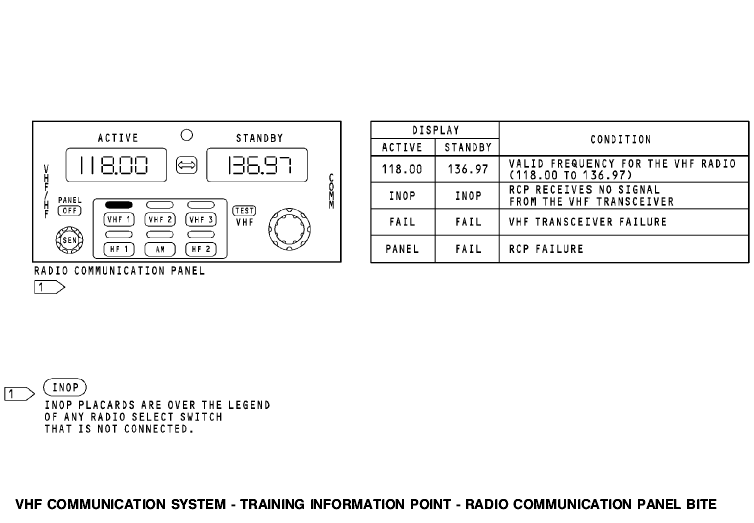
INOP INOP If the RCP receives no signal from the VHF transceiver, both displays show INOP. This occurs for these conditions: · There is no VHF transceiver · The VHF transceiver has no power · The VHF transceiver can not send ARINC 429 data to the RCP · The RCP does not receive the ARINC 429 data from the VHF transceiver · Wiring from the VHF transceiver to the RCP is bad.
If the RCP receives the FAIL WARN signal from the VHF transceiver, both displays show FAIL. This occurs when the BITE in the VHF transceiver senses that the transceiver has a failure. If the RCP has a failure, the active display shows PANEL and the standby display shows FAIL.
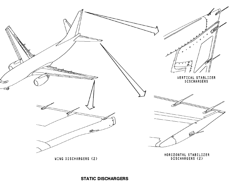
Static dischargers. Purpose There are static dischargers on the airplane to decrease radio receiver interference. The static dischargers discharge static at points as far from the fuselage as possible. This makes sure there is the least amout of coupling into the radio receiver antennas. Characteristics Each discharger has a carbon fiber tip at the end of a slender rod. The rod is a resistive (conducting) material and attaches to a metal base. The base attaches and bonds to the airplane surface. There are trailing edge and tip dischargers. The tip dischargers are smaller than the trailing edge dischargers. Location The vertical fin and each wing has a tip discharger and three trailing edge dischargers. Each side of the horizontal stabilizer has a tip discharger and two trailing edge dischargers.
Fig. 4.5. static dischargers Вопросы для самоконтроля. 1. Назначение УКВ радиостанции «Баклан-20». 2. Состав «Баклан-20». 3. Основные характеристики «Баклан-20». 4. Принцип действия «Баклан-20». 5. Органы управления и регулировки «Баклан-20». 6. Включение, проверка функционирования ««Баклан-20». 7. Индикация и сигнализация. 8. Какова дальность связи. 9. Вид модуляции. 10. Состав передающего тракта. 11. Состав тракта УНЧ. 12. Что происходит в ДПКД при изменении частоты на ПУ. 13. Состав тракта ПШ. 14. Когда ПШ подключает тракт УНЧ. 15. Какие каскады охвачены системой АРУ. 16. В каком диапазоне изменяется частота синтезатора в режиме приема. 17. В каком диапазоне изменяется частота синтезатора в режиме передача. 18. Какие сигналы сравниваются в ЧФД. 19. Назначение потенциометра «МОД». 20. Назначение потенциометра «СП». 21. Какие частоты вырабатывает ГУН. 22. Какие частоты вырабатывает опорный генератор. 23. Признак исправности приемного тракта. 24. Признак исправности передающего тракта. 25. Назначение, состав, основные характеристики VHF communication В737. 26. Принцип работы VHF communication В737. 26. Интерфейс VHF communication В737. 27. Включение, проверка функционирования VHF communication В737.
Рекомендуемая литература. Основная 1. Сосновский А.А., Хаймович И.А. Радиоэлектронное оборудование летательных аппаратов. Справочник – М.: Транспорт, 1987г. 2. Учебное пособие. Радиоэлектронное оборудование ЛА. Составитель Кукушин В.А. Академия ГА, 2007г. 3. Учебное пособие. COMMUNICATION СВЯЗНОЕ ОБОРУДОВАНИЕ BOEING 737-600/700/800/900. Training Manual. Составитель Кукушин В.А. Академия ГА, 2008г. 4. Учебное пособие. NAVIGATION. Part 1. НАВИГАЦИОННОЕ ОБОРУДОВАНИЕ. Часть 1. BOEING 737-600/700/800/900. Training Manual. Составитель Кукушин В.А. Академия ГА, 2008г. 5. Учебное пособие. COMMUNICATIONS СВЯЗНОЕ ОБОРУДОВАНИЕ А-320. Training Manual. Составитель Кукушин В.А. Дополнительная 1. Aircraft Aerodynamic, Structures and Systems. Module 13: M13.04 Communication Navigation (ATA 23/34); M13.06 Equipment and Furnishings (ATA 25) / EASA Part-66 Training Handbook. – LINK& LEARN Aviation Training GmbH, 2007. – 176 p. 2. Эксплуатационная документация на аппаратуру. (Технические описания. Инструкции по эксплуатации. АММ).
Тема 4. Very High Frequency (VHF) communication. УКВ-радиостанции. Цель лекции: Изучение УКВ-радиостанций. Вопросы лекции: 4.1. Назначение; 4.2. УКВ радиостанция «Баклан-20»; 4.3. Very High Frequency (VHF) communication; 4.4. VHF communications В737 и А320; 4.5. Static dischargers. Назначение. УКВ радиостанции (радиостанции СВЧ-связи) предназначены для ведения ближней телефонной симплексной радиосвязи экипажа самолета с наземными диспетчерскими службами УВД, а также для связи между экипажами самолетов, находящихся в воздухе. Они работает в диапазоне 118-137, 975 МГц, шаг частоты настройки 25/8, 33 кГц. Так как это основная связная система, на ЛА устанавливают, как правило, 2 или даже 3 комплекта аппаратуры. Соответственно имеется две антенны, одна – верхнего расположения (на нее работает основной комплект), другая – нижнего расположения (на нее работает второй комплект). |
Последнее изменение этой страницы: 2019-03-30; Просмотров: 1634; Нарушение авторского права страницы
 General