|
Архитектура Аудит Военная наука Иностранные языки Медицина Металлургия Метрология Образование Политология Производство Психология Стандартизация Технологии |
|
|
Архитектура Аудит Военная наука Иностранные языки Медицина Металлургия Метрология Образование Политология Производство Психология Стандартизация Технологии |
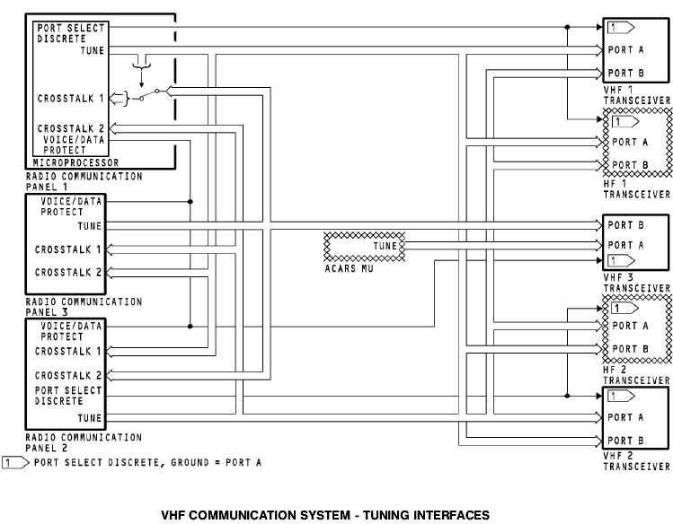
Training Information Point. If RCP 1 fails, you can tune the VHF 1 transceiver with RCP 2 or 3. These are the RCP VHF radio selections when the airplane receives power and there are no RCP faults
These are the RCP VHF radio selections when the airplane receives power and there are no RCP faults: · RCP 1 - VHF 1 · RCP 3 - VHF 3 · RCP 2 - VHF 2.
If RCP 1 fails, you can tune the VHF 1 transceiver with RCP 2 or 3. RCP 1 port select discrete changes from ground to open, and RCP 2 sends tuning data to input port B. RCP 3 sends tuning data on CROSSTALK 2 bus which connects to RCP 2. RCP 2 sends this tuning data to the VHF 1 transceiver on the output TUNE bus. If RCP 2 fails, you can tune the VHF 2 transceiver with RCP 1 or 3. RCP 2 port select discrete changes from ground to open, and RCP 1 sends tuning data to input port B. RCP 3 sends tuning data on CROSSTALK 1 bus which connects to RCP 1. RCP 1 sends this tuning data to the VHF 2 transceiver on the output TUNE bus. If RCP 3 fails, you can tune the VHF 3 transceiver with RCP 1 or 2. RCP 1 sends tuning data to RCP 2 on CROSSTALK 1 bus. RCP 2 puts RCP 1 tuning data on the output TUNE bus. RCP 2 output TUNE bus is connected to RCP 3 CROSSTALK 1 bus. The bus relay in RCP 3 is closed. The tuning data connects directly to the output TUNE bus and goes to the VHF 3 transceiver. RCP 2 tuning data goes to the RCP 3 CROSSTALK 1 bus and to VHF 3 transceiver on the output TUNE bus.
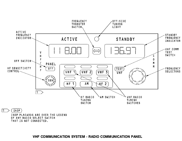
General The radio communication panel (RCP) provides these functions: · VHF and HF radio selection · Active/standby frequency selection · HF sensitivity control · Test initiation to the VHF transceiver · Mode selection to the HF transceiver · Off switch.
Controls and Indicators Any radio communication panel can control any transceiver. Push the radio tuning switch to select the transceiver for that radio communication panel. The light above the switch comes on. Each radio communication panel can tune only one transceiver at a time. неглавный When you select an off-side radio, two off-side tuning lights come on. One light is on the radio communication panel that you use to make the selection. This is the off-side radio. The other light is on radio communication panel of the radio you select. This is the on-side radio. Set the frequency in the standby frequency indicator. Turn the frequency selectors to set the frequency. The first digit is always цифра символ -- 1. The outer knob sets the second two digits (10 MHz and 1MHz) in 1 MHz increments. The inner knob sets the fourth, fifth, and sixth digits (100 kHz, 10 kHz, and 1 kHz) in 25 kHz increments. Внешний наружный ручка головка кнопка шаг приращение
Push the frequency transfer switch to change the active and standby frequencies. The HF SENS control sets the RF sensitivity level of the HF transceiver. Rotate the control to adjust the sensitivity of the HF transceiver. The inactive frequency indicator shows a value between 0 and 99. Maximum sensitivity is 99. Minimum sensitivity is 0. After a delay, the inactive frequency indicator shows the inactive frequency again. The VHF communication test switch starts a confidence check of the VHF transceiver. Push the VHF communication test switch to stop the squelch in the VHF transceiver. You hear static when you push the switch. Помехи сх. Бесшумной настройки Push the OFF switch to stop the operation of the radio communication panel. The switch shows white when it is off. BITE The radio communication panel continuously does a self-test. The frequency indicators show PANEL FAIL when there is an internal failure of the radio communication panel.
Purpose The purpose of the VHF transceiver is to transmit and receive information. Physical Description The transceiver is a solid state device. It has these components: устройство схема · Power supply · Frequency synthesizer · Receiver · Modulator · Transmitter · Microprocessor.
Functional Description The transceiver has these properties: · 118.000 to 136.975 MHz frequency range · Voice or data operation · 25 watts output power · Built-in fault detection and memory.
Power The transceiver operates with +27.5v dc. Controls, Indicators, and BITE Push the TEST switch to start a system self-test. This includes these tests: · Transceiver self-test · Input serial tuning word test последовательный периодический · Antenna VSWR test.
The front panel LEDs show the results of the VHF system selftest. These are the front panel LEDs: · LRU · CONTROL · ANTENNA.
The LRU LED shows a failure of the transceiver. The CONTROL LED shows a failure of the ARINC 429 input. The ANTENNA LED shows a failure of the antenna. All LEDs come on red for three seconds. Then the LRU LED changes to green and the other LEDs stay red for three seconds. Then the LRU LED comes on green for 30 seconds and the CONTROL and ANTENNA LEDs go off. The LRU LED comes on red after the self-test if there is a transceiver failure.
|
Последнее изменение этой страницы: 2019-03-30; Просмотров: 213; Нарушение авторского права страницы