|
Архитектура Аудит Военная наука Иностранные языки Медицина Металлургия Метрология Образование Политология Производство Психология Стандартизация Технологии |
|
|
Архитектура Аудит Военная наука Иностранные языки Медицина Металлургия Метрология Образование Политология Производство Психология Стандартизация Технологии |
Very High Frequency (VHF) communication.
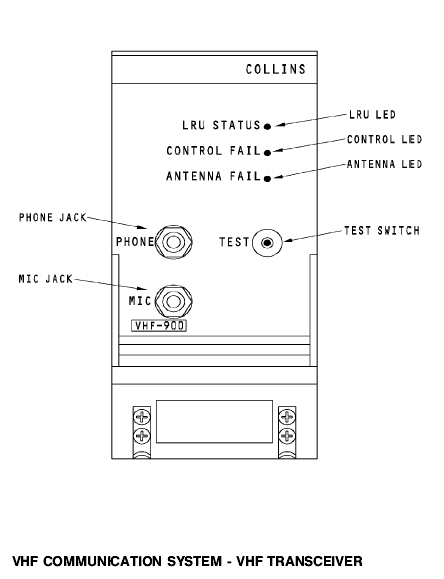
The VHF (Very High Frequency) communication system provides amplitude modulated short range (line of sight) voice communication between aircraft to aircraft and aircraft to ground. The frequency range allocated for commercial aviation VHF communication is 118.00 to 135.975 MHz, with 8.33 kHz spacing making a total of 720 channels. Average communication distance from the aircraft to ground is given by the formula Range (nm) A typical VHF system consists of a transceiver, control panel and an aerial. VHF Transceiver The transceiver is composed of a combination transmitter and receiver which share certain circuits. The frequency range is 118 to 136.975 MHz and the typical output power is between 25 and 40 watts.
Fig. 4.1. TYPICAL VHF COMMUNICATION TRANSCEIVER
The receiver is normally ON unless a push to talk circuit is completed. The received amplitude modulated signals are amplified, mixed and converted as necessary, then passed through the detector, squelch and amplifier circuits. Audio output of the receiver is fed to the audio selecting system through the VHF control panel volume control. The same selected frequency is used for both transmitting and receiving. Pressing a push-to-talk button energises the aerial relay which switches the aerial to the transmitter circuits. The transmitter is amplitude modulated by audio signals from the flight interphone system after crystal oscillator frequencies are mixed and multiplied as required to obtain the final output radio frequency. Transmitted audio is passed through the receiver and sent back to the transceiver sidetone output circuits where it is then connected to output circuits to the VHF control panel volume control and then to the audio selector panels.
Fig. 4.2. VHF COMMUNICATION SIMPLIFIED SCHEMATIC
VHF Control Panel The control panel provides frequency selection and frequency display for the VHF communication radios. It consists of a dual set of frequency selection knobs, a test button and a transfer switch.
Each section of the dual set of frequency knobs control the VHF system. A different frequency may be set up on each section. By positioning the transfer switch to the left, the frequency set up on the left will be used by the VHF transceiver and a transfer flag will negate the right frequency window. By positioning the transfer switch to the right it will cause the VHF transceiver to tune to the frequency set up on the right and the left window will be flagged. Pressing the COMM TEST button disables the receiver squelch circuits allowing an increase in background noise, thus indicating whether the receiver is operating correctly.
Fig. 4.4. TWO-OUT-OF-FIVE CODE
Frequency selection is by the two-out-of-five method. For any digit selected, two-out-of-five outputs will be connected to the frequency select common and the other three will be open. VHF Aerial The purpose of the VHF aerial is to radiate and intercept radio signals in the VHF frequency range. The aerial is vertically polarised, has an omnidirectional radiation pattern and has a 50 ohm impedance. A typical shark fin type blade aerial is shown in figure 4.5.
|
Последнее изменение этой страницы: 2019-03-30; Просмотров: 672; Нарушение авторского права страницы
 l, 3 aircraft height in feet.