
|
Архитектура Аудит Военная наука Иностранные языки Медицина Металлургия Метрология Образование Политология Производство Психология Стандартизация Технологии |
|
|
Архитектура Аудит Военная наука Иностранные языки Медицина Металлургия Метрология Образование Политология Производство Психология Стандартизация Технологии |
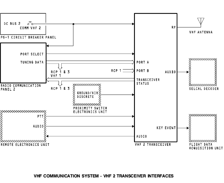
Radio Communication Panel
RCP 2 supplies frequency information to the VHF 2 transceiver on an ARINC 429 bus to port A. RCP 1 supplies frequency information to the VHF 2 transceiver on an ARINC 429 bus to port B. RCP 3 can supply frequency data to VHF 2 transceiver through RCP 1 or 2. For more information on tuning interfaces, see VHF Communication System - Tuning Interfaces. The VHF transceiver supplies the status of the transceiver to the RCPs.
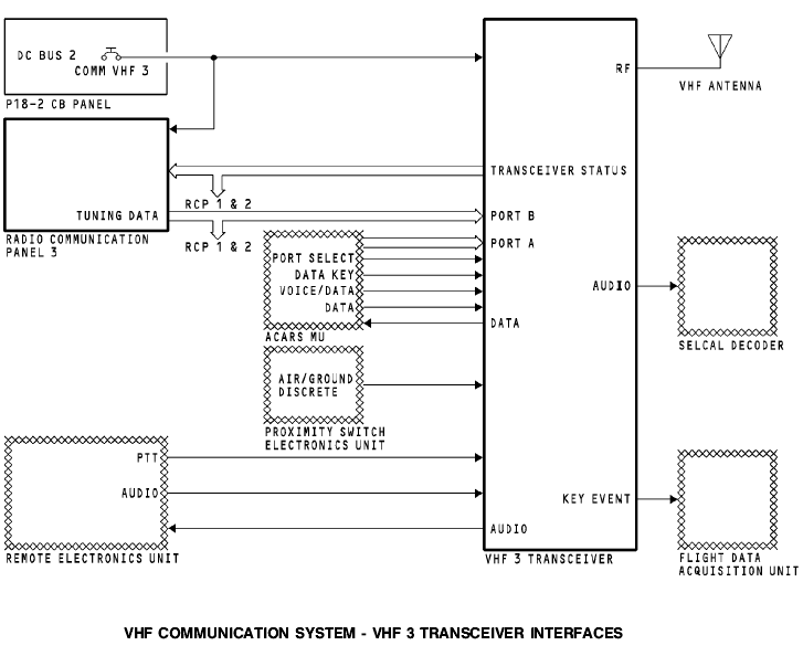
VHF Antenna The VHF antenna receives an RF signal from the VHF transceiver and transmits the RF signal to other airplane and ground VHF communication systems. The antenna also receives incoming RF signals and sends the RF signals to the VHF transceiver. The transceiver demodulates or detects the audio from the RF carrier signal. External Interfaces The VHF 2 transceiver has an interface with components from other airplane systems. The proximity switch electronic unit sends a ground signal to increase the flight leg count to track fault history. The remote electronics unit sends flight crew audio to the transceiver to be transmitted. It also sends a PTT start the transceiver transmit mode. The transceiver sends side tone and received audio to the REU for the flight interphone system. The transceiver sends received audio to the SELCAL decoder. The SELCAL decoder isolates the SELCAL code from voice audio. The flight data acquisition unit receives a PTT from the transceiver for key event marking. Power The DC bus 2 supplies 28v dc power to the VHF 3 transceiver and radio communication panel (RCP) 3. VHF 3 Transceiver The VHF 3 transceiver has an interface with these components: · RCP 1, 2, and 3 · VHF antenna · Proximity switch electronics unit · Remote electronics unit · SELCAL decoder unit · ACARS management unit · Flight data acquisition unit.
Radio Communication Panel RCP 3 supplies frequency information to the VHF 3 transceiver on an ARINC 429 bus to port B. The ACARS management unit (MU) sends tuning information to VHF 3 transceiver on an ARINC 429 bus to port A. For more information on tuning interfaces see VHF Communication System - Tuning Interfaces. The VHF transceiver supplies the status of the transceiver to the RCPs. VHF Antenna The VHF antenna receives an RF signal from the VHF transceiver and transmits the RF signal to other airplane and ground VHF communication systems. The antenna also receives RF signals and sends the RF signals to the VHF transceiver. The transceiver demodulates or detects the audio from the RF carrier signal. External Interfaces The VHF 3 transceiver has an interface with components from other airplane systems. The proximity switch electronic unit sends a ground signal to increase the flight leg count to track fault history. The remote electronics unit sends flight crew audio to the transceiver to be transmitted. It also sends a PTT to start the transceivers transmit mode. The transceiver sends received audio to the REU for the flight interphone system. The transceiver sends received audio to the SELCAL decoder. The SELCAL decoder isolates the SELCAL code from voice audio. The ACARS management unit sends these discrete signals to the VHF 3 transceiver: · Port select discrete to set the tuning data source · Data key to give a PTT signal · Voice/data to set transceiver voice or data mode. The ACARS management unit sends data audio to the VHF 3 transceiver to be transmitted to the ground station. The VHF 3 transceiver sends received data audio to the ACARS management unit. The flight data acquisition unit receives a PTT from the transceiver for key event marking.
The VHF communication system uses data buses to share tuning information between the radio communication panels (RCPs) and the communication transceivers. Tuning Bus Each RCP has one ARINC 429 output bus. The RCPs send tuning data to the communication transceivers. Any RCP can tune any transceiver. Each RCP sends tuning data and status to the other radio communication panels. This keeps the tuning data synchronized and lets any RCP tune any transceiver. The RCP keeps the tuning data in memory. Usually, the RCP uses the tuning data from its memory to send on the output bus. The RCP can connect the CROSSTALK 1 bus directly to the output bus. This occurs for these RCP conditions: · RCP does not have power · RCP is OFF · RCP is failed. Port Select Discrete RCP 1 and 2 send the port select discretes to the transceivers. The ACARS MU sends a port select discrete to the VHF 3 transceiver.
The RCPs send the voice/data protect discrete to the VHF 3 transceiver. This discrete selects either the ACARS management unit or the RCPs to tune the VHF 3 transceiver. Each transceiver has two tuning data input ports, port A and port B. The transceiver uses the port select discrete to select the input port. A grounded port select discrete causes the transceiver to use port A. An open port select discrete causes the transceiver to use port B. |
Последнее изменение этой страницы: 2019-03-30; Просмотров: 218; Нарушение авторского права страницы
 General