
|
Архитектура Аудит Военная наука Иностранные языки Медицина Металлургия Метрология Образование Политология Производство Психология Стандартизация Технологии |
|
|
Архитектура Аудит Военная наука Иностранные языки Медицина Металлургия Метрология Образование Политология Производство Психология Стандартизация Технологии |
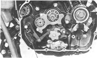
G EA RSH IF T LINKAG E R EM O V A L
Remove the right crankcase cover and clutch as· sombly (Section 7).
Remove the oil pump driven sprocket bolt.
Remove the oil pump drive chain, drive and driven sprockets.
Remove the outer guide and collar.
(2)0IL PUMP DRIVE
(3) OIL PUMP DRIVEN SPROCKET (4) BOLT
Pull tho gearshift spindle assembly out.
(1IGEARSHIFT SPINDLE
GEARSH I FT LINK AG E VT500C
GEARSHIFT LINKAGE INSTALLATION I nstall the drum stopper arm, bolt and retu rn spring.. Tighten the bol t.
TORQ UE : 8-12 N·m (0.8-1.2 kg·m, 6-9 ft·l b)
Align the hole i n the stopper plate base plate with the p in on the shif t drum.
Set the stopper plate by l ilting the stopper arm with a screw driver and tightening the stopper pla te bol t.
TOR QUE : 10-14 N·m (1.0-1.4 kg-m , 7-10 ft lb)
I nstall the goar shift spindle as shown. Rotate the gear shift spindle and check the linkage f or smooth operation.
{1)GEA RSHIFT SPINDLE
(l)CLUTCH OUTER GUIDE
Install the oil pump drive and driven sprockets with drive cha in and tighten the driven sprocket bolt.The driven sprocket "IN" mark must face the crankcase.
TORQUE : 8-12 N ·m (0.8-1.2 kg·m, 6-9 ft-lb) Install the clutch assembly and right crankcase cover (Section 7). ( 1) OIL PUMP
(2) 0 AIVE SPROCKET
CYLINDER HAD/VALVE H ONDA
'- \ ---- (0.8-1.2 kg·m, 6-9 ft·lb)
(2.0-2.5 kg·m, 14-18 ft·lb)
20-25 N·m (2.0-2.5 kg·m, 14-18 ft-lb)
8-12 N·m (0.8-1.2 kg·m. 6-9 ft-lb)
CYLINDER H EAD/VALVE
CY LI NDER HEAD COVER REM OVA L Remove the engi ne from the f rame ( page S.2).
Remove the water pipes from the front and rear cylinder heads.
R emove the O·rings from the water pipes.
Remove the val ve adjuster caps and covers.
., ,. I • VT500C (1)
Remove the cylinder head cover bolts and cover. (1) VALVE ADJUSTER CAP AND COVER
(1)
CAMSHAFT HOLD ER REMOVAL Remove the two bol ts and oil p·assage. R:emove the camshaft holders. VTSOOC (2)
R emove the rocker arm shafts by tapping the holder with a plastic hammer.
R emove the rocker arm and wave washers from the shafts.
(1) ROCKER ARM SHAFTS
(1) ROCKER ARMS
(2) WAVE WASHERS
CY LINDER HEAD/VALVE H ONDA VTSOOC
ROCK ER ARM INSPECTION
NOTE
Measure the 1.0. of each rocker arm.
SERVICE LIMIT: 12.05 mm (0.474 in)
Inspect rocker arm shafts for wear or damage and measure the 0.0.
SERVICE LIMIT :11.83 mm (0.466 in)
Calculate the rocker arm·tO·shaft clearance. SERVICE LIMIT: 0.22 mm (0.009 in)
CAMSHAFT REMOVAL
(1) ROTOR TIMING MARK
(2) INDEX MARK
CYLINDER H EAD/VALVE H O NDA
Measure the amount of the cam chain tensioner pro jects as shown. Replace the cam chain with a new one if the projection exceeds 9.0 mm (0.35 in).
To replace the cam chain, drain the oil from the engine and remove the following parts:
Pull wedge A straight up while holding wedge B down. Secure wedge A w ith a 2 mm pin as shown.
Remove the cam sprocket bolts. Rotate the crankshaft clockwise one turn (360°) and remove the other cam sprocket bolts.
NOTE
Be careful not to let the cam sprocket bolts fall into the crankcase.
Remove the cam sprocket from the camshaft flange with the cam chain.Rotate the crankshaft clockwise half a turn (180°) and remove the cam chain from the sprocket.
Hang the cam chain on the camshaft behind the camshaft flange. Remove the cam sprocket while lifting the camshaft out.
Attach a piece of wire to the cam chain to prevent it from being dropped into the crankcase. (1) PIN
(1) CAM SHAFT (21 CAM CHAIN
(31 CAM SPROCK ET
CAMSHAFT HOLDER/CY LINDER HEAD
Inspect the camshaf t holder and cylinder head journal surfaces for scoring, scratches, or evidence of insufficient lubrication.
Check camshaft runout with a dial indicator. Support both ends of the camshaft with V-blocks. Use 1/2 of the total indicator reading to determine run ou t. SERVICE LIMIT: 0.05 mm (0.002 in)
CAM LOBE HEI G HT Using a micrometer. measure the heigh t of each cam lobe.
SERVICE LIMITS: IN: 38.00 mm (1.496In) EX : 37.90 mm (1.492 in)
CAMSHAFT INSPECTION Check the camshaft journals for wear or damage. Measu re the 0.0. of each jou rnal.
SERV ICE LIMITS : 21.826 mm (0.859 in)
Wipe any oil from the journals .Lay a strip of plastl · gauge lengthwise on top of each camshaft jou rnal.
NOTE
Avoid placing plastigauge over the oil hole in the cam holder.
Hook the cam chain suspension wi re against the cam chain guide.
(1)
Install the camshaft holder's and tighten in a criss· cross pattern in 2-3 steps.
NOTE
Do not rotate the camshaft when using plati· gauge.
TORQUES: 6 mm bolt/nut: 20-25 N-m (LEFT) (2.0-2.5 kg·m, 14-18ft lb) 6 mm SH bolt: 8-12 N·m (RIGHT) (0.8-1.2 kg·m. 6-9 ft-lb)
SERVICE LIMIT :0.23 mm (0.009 in)
When the service limits are exceeded,replace the camshaft and recheck the oil clearance.
Replace the camshaft holders if the clearance still exceeds the service limits.
Remove the carburetor intake pipes. Remove the oil bolts from the front and rear cylin· der heads. (1) 6 mm BOLTS
(2) 6 mm NUT
CYLINDE R HEAD/VALVE H O NDA. VT500C
Remove the oil pipe holding bolt and lower oil bolt. Remove the oil pipe.
Remove the upper cam chain tensioner bolt and copper washer.
Loosen the lower cam chain tensioner bolt.
Remove the 10 mm nuts, 8 mm nuts, 8 mm bolt and 6 mm cylinder bolt. Remove the cylinder head. (1) BOLT
(2) 01L PIPE (3) LOWER OIL BOLT AND WASHERS
(1) UPPER CAM CHAIN TENSIONER BOLT
(2) LOWER CAM CHAIN TENSIONER BOLT
Remove the cylinder head gasket and dowel pins.
|
Последнее изменение этой страницы: 2019-06-10; Просмотров: 223; Нарушение авторского права страницы
 (llOIL PUMP
 Remove the drum stopper arm bolt,arm and spring. Remove the roller stopper plate bolt and plate.


 Install the clutch outer guide over the main shaft.
 DRIVE CHAIN
 VT500C
 1 8-12 N·m
 20-25 N-m


 CYLINDER HEAD COVER
 CYLIN DER HEAD / VALVE


 Inspect the rocker arms for damage. wear or clog11ed oilholes.
 ROCKER ARM SHAFT INSPECTION
 VT500C


 INSPECTION
 CAMSHAFT RUNOUT

 NOTE
NOTE

 PLASTIGAUGE
 Remove the camshaft holders and measure the width of each plastigauge. The widest thickness determines the oilclearance.
 CYLINDER HEA D REMOVAL


 (1l10 mm NUTS (2) 8 mm NUT