
|
Архитектура Аудит Военная наука Иностранные языки Медицина Металлургия Метрология Образование Политология Производство Психология Стандартизация Технологии |
|
|
Архитектура Аудит Военная наука Иностранные языки Медицина Металлургия Метрология Образование Политология Производство Психология Стандартизация Технологии |
CRANK S HAFT /T R ANSM I SS I O N
VT500C
OUTPUT DRIVE GEAR R EMOVAL
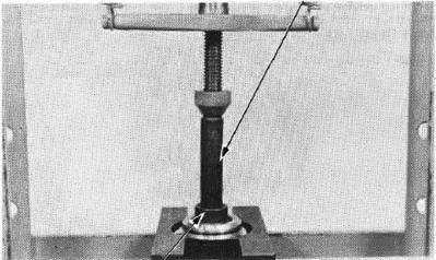
Place the output gear case in a vise with sof t jaws, being careful not to distort it.
Place the shaft holder tool on the driven gear shaft wedging it against the vise to lock the shaft.
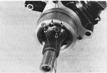
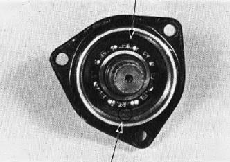
U nstake the in ner bearing race lock nut and outer race lock nut with a drill or grinder. Be C.'lreful that metal particles do not enter the bearing and the th reads on the shaft are not damaged. (1lLOCK NUTS
(2) UNSTAKE
(1) SHAFT HOLDER
(2) LOCK NUT WRENCH
Remove the beari ng outer race lock nut. (1) LOCK NUT WR ENCH 36 x 4B mm 07916-MBOOOOO
(2) BEARING OUTER RACE LOCK NUT.
Remove the lock washer. Remove the output drive shaft. (1) OUTPUT DRIVE SHAFT
(2) SLIDER HAMMER
(3)
OUTPUT DRIVE SHAFT BEARING REPLACEMENT
Remove the output drive shaft bearing from the output drive shaft with the bearing puller.
(1I BEARING PULLER
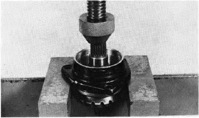
Place the adjustment shim between the bearing and drive shaft gear (Page 13-18). Hold the bearing inner race with attachment. Press the output drive shaft into the bearing. NOTE
Place the pilot's threaded end into the final drive shaft.
(1) PILOT,25 mm 07746-0040600
(2) ATTACHMENT, 30 mm 07746-0030300
Press the output drive shaft assembly into the out· put gear case. (t) DR IVER C 07746-00201co (2) ATTACH MENT, 30 mm 07746-00303)()
I nstall the lock washer Into the case wi tt1 its "NUT" mark facing nut.
Clean the bea ring outer race lock nut threads throughly. Place the case into a vice with soft jaws.
Install and ti!titen a new bearing outer rece lock nut. The drive shaft assembly \!Viii also be installed at the same time.
TORQUE WRE NCH SCALE READI NG: 80-100 N·m (8.0-10.0 kg-m, 68-72 ft lb) ACTUAL TORQUE APPLIED: 90-110 N·m (9.0-11.0 kg-m, 65-80ft lb) (1) "NUT" MAR K
(1) LOCK N UT WRENCH 30/64 mm 07916-MBOOOOO
(2) BEARING OUTER RACE LOCK NUT
CRANKSHA FT/TRANSMISSION
I nstall and tighten a new inner race lock nut to the specified torque.
TORQUE WRENCH SCALE READING: 64-73 N•m (6.4-7.3 kg-m, 46-53 ft·lb) ACTUAL TORQUE APPLIED: 70-80 N·m (7.0-8.0 kg-m, 61-68 f t-lb)
Stake the inner and outer lock nuts.
(2) SHAFT HOLDER 07924-MESOOOO H ONDA
11) LOCK NUT WRENCH
OUTPUT DR IVEN GEAR REMOVAL
Remove the driven gear oil seal from the ou.tput driven gear case.
Place the output driven gear case i nto a vise.
Unstake the inner bearing race lock nut and the outer bea ring race lock nut with a drill or grinder.
(11 LOCK NUTS
Remove the output driven gear beari ng inner race lock nu t.
Remove the 0-ring.
(11 LOCK NUT WRENCH 34 x 44 mm 07916-ME50000
(2) SHAFT HOLDER 07924-ME50000
OUTPUT DRIVEN GEAR BEA RING R EPLACEMENT
Place the outpu t driven gear bearing holder in to a vise wi th soft jaws. Remove the outpu t driven gear bearing outer race lock nut from the holder.
Remove the lock washer.
Press the output driven gear shaft from the holder.
Press the bearing out of the holde r.
NOTE
Be careful not to damage tne bearing holder
(1} LOCK NUT WRENCH 34/44 mm .07916-MESOOOO
11} DRIVER A 07749-0010000
(2} ATTACHMENT 52 x 55 mm 07746-0010400 (3) PILOT 30 mm 07746-0040700
Press in a new bearing and make sure it rotates freely after installation. (1) DR IVE R 07749-0010000
(2) ATTACHME NT, 52 x 55 mm 07746-0010400
(1) DR IVER, B 07746-0020100
.. (2) ATTACHMENT, 17 mm l.D. 07746-0020300
Place the output driven gear bearing holder into a press. Then press in the output driven gear. Support the inner bearing race using the special tools.
Install the 0-ri ng and correct shim.
I nstall the lock washer with i ts "NUT" mark facing the lock nut.
(3) ATTACHME NT,30 m m l.D. 07746-0030300
(1) LOCK WASHER
(2)"NUT" MAR K
Place the bearing holder into a vise with soft jaws. I nstall and tighten a new bearing outer race lock nut |
Последнее изменение этой страницы: 2019-06-10; Просмотров: 281; Нарушение авторского права страницы

 Remove the inner bearing race lock nuts and discard them.
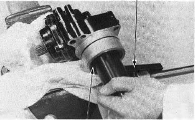
 BEARING REMOVER 07936 -8890001
 j
j


 OUTPUT DRIVE GEAR INSTALLATION


 VT500C
 36 x 48 mm 07916-MBOOOOO
 (!)STAKE
 (1)01L SEAL
 (21UNSTAKE
 Remove the driven gear bearing holder mounting bolts and remove the shim, gear and holder from the case.
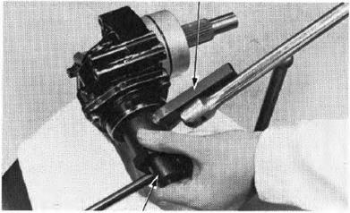


 gear case mating surface.


 NOTE
NOTE
 •
•