
|
Архитектура Аудит Военная наука Иностранные языки Медицина Металлургия Метрология Образование Политология Производство Психология Стандартизация Технологии |
|
|
Архитектура Аудит Военная наука Иностранные языки Медицина Металлургия Метрология Образование Политология Производство Психология Стандартизация Технологии |
FINAL DRIVE INSTALLATIO N
Apply multipu rpose grease to the pin ion jo int splines and drive shaft oil seal.
I nsert the drive shaft in to the swingarm and align its splines with the u niversal jo int.
(1) STOP RING (2) OIL SEAL
Arm. NOTE
Attach the gear case onto the swingarm loosely.
NOTE
TORQUE : 50-80 N·m (5.0-8,1() kg-m, 36-8ft-lbl Tighten the axle pinch bolt. TORQUE: 20-30 N·m (2.0-3.() kg-m, 114-22 ft-lb) Tighten the four final gear case attaching nu ts.
TORQUE:20-24 N·m
Place the motorcycle on i ts cen ter stand. Make sure that the drain bolt is tightened. Remove the oil filler cap and pour the specif ied amou nt of recom mended oil up to the filler neck.
RECOMMENDED OIL: HYPOID GEAR OllL Over 5°C: SAE 90 Below 5°C: SAE 80
OIL CAPACITY: 150 cc (5.1oz)
(3) DRAIN BOLT
20-30 N·m (2.0-3.0 kg m, 14-22 ft lb)
15-30 N·m --(1.5-3.0 kg-m, 11-22 ft lb)
18-28 N·m (1.8-2.8 kg m, 13-20 ft-lb)
45-55 N·m (4.5-5.5 kg m, 33-40 ft-lb)
55-65 N·m (5.5-6.5 kg m, 40-47 ft lb)
18-28 lll·m (1.8-2.8 kg·m, 13-20 ft·lb)
30-40 N·m (3.0-4.0 kg m, 25-29 ft·lb) FRONT WHEEL/SUSPENSION VT500C
CASE REMOVA L
Remove the headlight mounting screw. Disconnect the wire coupler and remove the head· ligh t.
To remove the headlight case, unscrew the headlight case mounts.
(2) SCREW
BULB REPLACEMENT
Remove the clip and head light bulb .
Install a new headlight bulb and install the clip .
CAUTION
Route the wires into the headlight case through the headlight case hole. Connect the color-coded wires and couplers. (1) HEADLIGHT BULB (2) CLIP
CASE INSTALLAT ION
Align the index marks on the headlight .case stays with the index marks on the brackets.
BRACKET R EMOVAL/ INSTALLAT ION
Remove the headligh t case. Remove the headlight bracket bolts and bracket/ turn signal assembly.
Install the headlight bracket in the reverse order of removal.
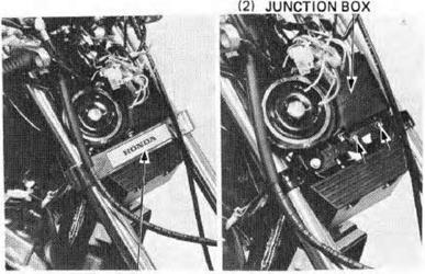
I NSTRUMENTS Remove the headlight case. Remove the fork cover and electrical junction box from the steering stem. Remove the brown coupler from the ju nction box.
COUPLER c::JD D
(1) INDEX MAR KS
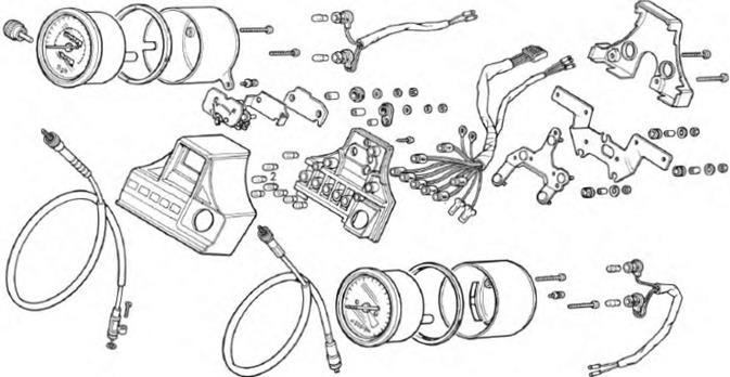
Remove the instrument mounti ng nuts and instru ments.
DISASSE MBLY
Remove the instrument lower cover mounting screws and lower cover.
(1) TACHOMETER CABLE (2) SPEEDOMETER CABLE
Remove the instru ment bulbs and replace any burnt out bul bs. After installing a new bulb, check to be sure it lights. I f the bulb doesn't light, inspect the wiri ng for an open or short circuit.
Remove the meter setting screws and meter.
Replace the bulb. I f a replacement bulb does not light, check the wi r· ing for an open circuit or loose connections.
(2) (1) BULB
ASSEMBLY/INSTALLATION
Lubricate the speedometer and tachometer cables before reconnecting .
Reassemble and install in the reverse order of re· moval and disassembly. ...
NOTE
R emove the handlebar switch mounting screws and throttle cables.
Disconnect the switch wi res from the switch.
Remove the headlight case, fork -cover and junction box.
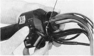
Disconnect the righ t handlebar switch coupler !Natural) from the junction box and remove the switch.
I nstall a new switch aligning the switch pin with the hole in the handlebar. Tighten the forward screw first, then tighten the rear $Crew. Check the opera· tion of the switch. After i nstall i ng, adjust th rottle cable free play (page 3·5).
H ANDLEBARS REMOVAL
Remove the harness wire bands. Remove the headlight case {page 15 3), fork cover and junction box (page 15-4).
Remove the brake master cylinder.
CAUTION
NOTE
Do not loosen the brake hose u nless necessa ry.
(2)
Remove the choke lever holder and disconnect the choke cable from the chock lever.
Remove the tour caps and handlebar holder mou nt· ing bol ts.
Remove the hand lebar holders and handlebar.
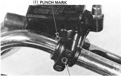
Place the handlebar on to the lower holder align ing the punch mark wi th the oUt$ide face of the lower holder.
TORQUE: 20-30 N·m (2.0-3.0 kg m, 14-22 ft·lbl
FRONT WHEEL /S USPENSION Apply grease to the throttle grip sliding surface and slide the throttle grip over the handlebar.
I nstall the front brake master cylinder wi th the 'UP' mark on the holder facing up. Align the end of the holder wirh the handlebar punch mark.Tighten the upper bolt first. then the lower bolt.
Install the right handlebar switch and connect the brake light swit<:h wires (page 15-7).
Tighten the upper bolt first, then the lower bolt. I nstall the left handlebar switch and connect the clutch switch wires (page 158). H O NDA
(2) "UP" MAR K
FRONT WHEEL/SUSPENSION H ONDA VT500C
CHOKE CABLE REPLACEMENT
Remove the choke lever holder and disconnect the choke cable from the choke lever.
Remove the fuel tank ( page 4-J4). Remove the choke cable boots and loosen the choke valve nuts on the carburetors. Remove the choke val ve from the carburetor. Remove the choke cable from the choke valve. Lubricate the new choke cable.
THROTTLE CABLE REPLACEMENT
Remove the righ t handlebar switch housing (page 15- 7). Remove the th rottle cables from the th rottle grip. (1) CHOKE CABLE
Remove the throttle linkage cover. Remove the throttle cables fTom the carburetor throttle pulley.
Attach new cables to the throttle pulley. Reinstall the throttle linkage cover. Route the new cables correctly (page 1-9). Attach the cables to the th rottle grip. Reinstall the switch housing ( page 15-8). Adjust the th rottle free play (page 3-5).
IG N ITIO N SWIT C H REMOVAL/ INSTA LLATION
Remove the headlight and headlight case.
Remove the fork cover ju nction box-and two white couplers from the junction box (page 1- 11).
Remove the ignition switch mounting bolts, and ignition switch.
Install the ignition switch in the reverse order of re moval.
DISASSEMBLY/ASSEMBLY
Bend the wire clamp tongue u p.
(1)
(1)
Insert tht ignition key and tu rn it to between the ON and OFF detent positions.
Push In the lugs In the slots and pull the contact Base from the switch.
(1) SLOTS
• •
- (2) LUGS
REMOVAL/INSTALLATION
Remove the headlight and nead light case. Remove the fork co\er and junct ion box from the steering steem. Disconnect the fuse holder coupler from the junction box (page 1-11).
Remove the fuse holder cover mounting screws and the cover .
I nstall a new holder. route the wire harness and attach i t to the junction box . Reinstal l the removed parts.
REMOVAL
R aise the front wheel off the ground by placing a support block under the·engine.
Disconnect the speedometer cable by removing the speedometer cable set screw.
CABLE
Loosen and remove the front axle and remove the front wheel.
NOTE
Remove the brake disc mounting bolts and discs.
{2) SEAL
Remove the left seal and speedometer gear retainer.
{ 11 SEAL
(2) SPEEDOMETER GEAR RETAINER
I nstall the bearing remover collet, 15 mm into the bearing.
Drive the bearing remover expander into the collet from the other side of the bearing.
If the bearings are removed, they should be replaced with new ones.See inspection on the next page. (1) BEARI NG R EMOVER COLLET, 15mm 07746-0050400
(1) 07746-0050100
Check wheel bearing play by placing the wheel i n a truing stand and spinning the·wheel by hand.
Replace the bearings if they are noisy or have exces- sive play. '
SERVICE LIMIT:0 03 mm (0.001in)
SERVICE L MITS: RADIA L RUNOUT: 2.0 mm (0.08 in) AXIA L RUNOUT: 2.0 mm (0.08 in)
The wheel cannot be repaired and must be replaced with a new one if the service limits are exceeded.
Set the axle in V blocks and measure the runout. The actual runout is 1/2 of the total indicator reading.
SERVICE LIMIT: 0.2 mm (0.01lnl
ASSEMBLY
NOTE The cast wheel has no rim band. The front wheel uses a tubeless tire. For tubeless tire repa ir, refer to the Honda Tubeless Tire Manual.
(1) DRI VER
NOTE
Be certain the distance collar is in position before installi ng the right beari ng.
Install the left seal.
I nstall the brake disc and tighten the bolts to the specified torque value .
TORQUE:35-40 N·m .3.5-4.0 kg-m, 25-29 ft-lbl
NOTE
Mount the wheel, tire and brake disc assembly in an inspection stand.
Spin the wheel, a llow it to stop, and mark the lowest (heaviest) pa rt of the wheel with chalk. Do this two or three times to verify the heaviest area. If the wheel is balanced, it will not stop consistently in the same position.
I nstall the speedometer gearbox in the wheel hub, -liyning the tabs with the slotS.
Clean the brake discs with a igh quality degreasing agent.
Place the wheel bet'Nff n the fork legs. Fit the disc carefully between me brake pads.
Align the speedometer 119arbo with the boss on the left fork leg as shown.
I nstall the axle and collar. Remove the support block f rom under the engine.
TORQUE:55-65 N m (5.5-6.5 kt-m.4G-47 ft-lb)
Tighten the axle pinch bolt to the specified torque.
TORQUE:18-28 N·m (1.8-2.8 kg·m, 13-20 ft-lb)
lnstell the speedometer cable and set screw.
(1) FRONT FORKS Remove the front wheel (page 15-141. Remove the brake caliper bracket.
Remove the front fender and fork brace.
Loosen the fork upper and lower pinch bolts. Pull the fork tubes down and out while twisting to remove them .
(1)
Depress the air valve and release front fork air pres Sure. CAUTION
Drain the fork oil by removing the drain plug.
CAUTION
(1) DRAIN PLUG
Remove the collar, washer and fork spring. Pour the fork fluid out. Pour the remaining fork fluid out by pumping the fork tube several times.
Hold the fork sl der in a vise with soft jaws or a shop towel. Remove the socket bolt with a hex wrench.
NOTE
Temporarily install the spring and fork cap if the bolt is difficult to remove.
Remove the dust seal, foam washer,plastic washer and snap ring.
(2) SNAP RING
Remove the oil lock piece from inside the slider.
NOTE
BUSHING
BUSHING
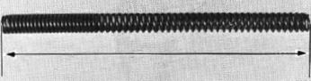
INSPECTION FOR K SPRING F REE LENGTH
Measure the fork spring free length.
SERVICE LIMIT:447 mm (17.6 in)
Replace the spring If it is shorter than the service limit.
15-25
Check the fork piston ring for wear or damage. Check the rebound spring for fatigue or damage,
SERVICE LIMIT:0.2 mm (0.01In)
Visually inspect the slider and fork tube bushings. Replace the bush ing if there is axoessiva scoring or scratching, or if the tef lon is worn so that the copper surface appears on more than 3/4 of the entire surface.
Check the back.up ring. Replace it if thereo is any distortion at the points shown.
(1)
...,,'
'.... ...
(2) (4) CHECK POINTS --++--"" COPPER SURFACES
15-26 FRONT WHEEL/SUSPENSION CiiJ\H O NDA VTSOOC
ASSEMBLY
(1) FORK CAP BOLT-----
(2) COLLAR
(3) SPR ING
(4) PISTON --- RING
(5) PISTON
Install the bushing onto the inner tube.
Install the piston, rebound spring and oil lock piece into the fork tube. Apply a locking agent to the bolt threads and under side of the bolt, then tighten the bolt.
TORQUE:15-25 N·m (1.6-2.5 kg·m, 11-18 ft-lb)
CAUTION
(7) DUST SEAL (8) FOAM WASHER (9) PLASTIC WASHER (10) SNAP RING (11) ,.,..-----,OIL SEAL .... (12) --------BACK-UP RING (13) ------SLIDER BUSHING
(14) !-----_:..:_ FORK SLIDER
(15) ..- ---- SOCKET BOLT
FORK TUBE BUSHING (17) OIL LOCK PIECE
Install the snap ring with its radiused edge facing down.
Install the plastic washer, foam washer and dust cover.
Pour in the spaeifi9d amount of ATF. SPECIFIED FLUID: ATF CAPACITY: 390 ± 2.5 cc (23.8± 0.1Scu in)
(1)
Do not overfill or the suspension will be too stiff.
Insert the fork spring Into the fork to be with the narrow (tight) windings towards the top.
Place the washer and collar on top of the fork spring.
TORQUE: 15-30 N·m (1.5-3.0 kg-m, 11-22 ft-lb)
NOTE
Be sure that the top of ea<:h tube is f lush with the top of the fork bridge.
Tighten the fork bridge and steer ing stem pinch bolts on one side.
TORQUE VALUES: Fork bridge: 9-13N·m (0.9-1.3 kg-m, 7-9 ft lb) Steering stem: 45-55 N·m (4.5-5.5 kirm. 33-40 ft-lb)
Install the fork brace hex bolts loosely.
NOTE
On not tighten the fork brae<! at this time.
I nstall the front fender and brake caliper bracket. Tighten the caliper bracket mount bolt.
TORQUE: 30-40 N·m (3.0-4.0 kg·m, 22-29 ft-lb)
I nstall the front wheel (page 15-20). Tighten the fork brace hex bolts to the specif ied torque.
TORQUE: 18-28 N·m (1.8-2.8 kg-m, 13-20 ft·l b)
Fill the fork tubes with ai r to 0-40 kPa (0--0.4 kg/cm1, 0-6 psi I,with the motorcyde on its center stand.
CAUTION
With th t front brake applied, pump the front forks up and down several times. Place the motorcycle on its center stand . Check the air pressu re and adjust if necessary .
STEERING STEM REMOVAL
Remove the following parts: - headligh t, headlight case and bracket (page 15 3). - instrumen ts (page 15-4). - handlebar (page 15-8). - fron t wheel ( page 15·14). - caliper bracket ( page 17-13). - horn bracket. - electrical junction box (page 15-4).
R emove the steering stem/bridge n ut. Remove the front forks (page 15-21). Remove the fork bridge.
(11 LOCK NUT WRENCH. 30 K 32 mm, 07716-0020400
Remove the stHring stem adjusting nut, steering stem and steel balls .
Remove the lower cone race and dust seal.
I nstall a dust seal and drive the lower cone race on with the steering stem driver (No. 07946-MBOOOOO or 07946-37 10601 and 07964-MB00200). (1IPIN SPANNER
(1)
Inspect the top and bottom ball races and replace if worn or damaged. Remove the upper ball race with the special tool.
NOTE
Remove the sliding guide from the bearing Ra ce remover.
NOTE
Drive the upper ball race into the head pipe with the special tools.
Drive the lower ball race into the head pipe with the special tool.
(1)
INSTALLATION
Apply grease to the bottom bal l race and install 19 ball bearings.
Insert the steering stem into the steering head pipe and install the top cone race.
I nstall the bearing adjustment nut and tigh ten it snug against the top cone race. Then , back it off 1/8 turn. Make sure that there is no vertical movement and that the stem rotates freely.
ADJUSTMENT NUT
I nstall the front forks and tighten the stem n u t.
TORQUE:90-120 N·m 19.0-12.0 kg·m, 65-87 ft-lb I
I nstall the removed parts in the reverse order of removal. ( 1) LOCK NUT WRENCH,30 x 32 mm BRAKE VT500C
R EAR WHEEL REMOVAL
Place the motorcycle on its center stand and loosen the axle nut.
Remove the brake torque link bolt and disconnect the torque link.
Remove the brake adjusting nut and the brake rod.
Loosen the axle pinch bolt and remove the rear axle.
(1) AXLE NUT
':
,. r.
Remove the final driven flaroge mount bolts and lift the driven flange out of the hub.
Remove the wheel bearings and distance collar with the special tool.
INSPECTION AX LE Set the axle in V blocks and read the axle runout with a dial indicator. The actual axle runout is 1/2 of the totalindicator reading.
SERVICE LIMIT:0.2 mm (0.01 in) (1) WHEE L BEARING REMOVER COLLET, 17 mm 07746-0050500
(2) BRAKE VT500C
SERVICE LIMIT:0.03 mm (0.001In)
Check the rim for runout by placing the wheel in a truing stand. Spin the wheel slowly, and read the runout using a dial indicator.
SERVICE LIMITS: RADIAL RUNOUT:2.l() mm (0.08 in) AXIAL RUNOUT: 2.•0 mm (0.08in)
The wheel cannot be serviced and must be replaced if the above limits are exceeded.
Measure the brake drum I.D.
SERVICE LIMIT:161 mm (6.34 in)
BRAKE VTSO OC
NOTE
.. Pack all bearing cavities with grease.
Press the distance collar into place from the left side. Drive the left ball bearing i n first, then the right ba ll bea ring.
CAUTION 0 11)
.--
l'ILOT. 17 mm 07746-0040400
I nstall the final driven f lange onto the rear wheel and tigh ten the bolts.
TOR QU E: 50-60 N·m (5.0-6.0 kg-m, 36-43 ft·lb)
INSTALLATI ON
Apply Multipurpose NLGI No. 2 grease (MoS2· additive) to the f1nal driven flange and ring gear engagement splines.
Loosen the final gear case attaching nuts to eue axle installation and to assu re proper driven flange align ment.
Engage the rear wheel with the final drive case, making sure the splines are correctly aligned.
Wedge a f lat screwdriver ti p into the pinch bolt slot.
Insert the rear axle through the swing arm, side collar, brake panel, hub and final drive gear. Turn the axle and check that it rotater freely.
Remove the screwd river from the pinch bol t slot. Tighten the axle n ut to the ified torque. TOR QUE: 50-80 N·m (5.0-8.0 kg m, 36-58 ft lb) (1) FINAL DR IVEN F LANGE
(1)
REAR WHEEL/SUSPENSION BRAKE H O NDA VTSOOC
Tigh ten the axle pinch bolt.
TORQUE: 20-30 N·m (2.0-3.0 k11-m, 14-22 ft-lb)
Place the brake rod through the brake arm pin and install the brake adjusting nut.
Tighten the brake torque link bolt.
TORQUE: 15-25 N·rn (1.5-2.5 k11-m, 11-18 ft-lb)
Adf ust the rear brake (page 3·'14) .
REAR BRAKE PANEL LINING THICK NESS INSPECTION
Measure the rear brake lining t hickness. SERVICE LIMIT:2.0 mm (0.08 in) Replace the brake shoes if they are thinner than the service limit.
DISASSEMBLY
Remove the rear brake arm. Remove the cotter pins and brake shoes.
ASSEMBLY
Apply grease to the anchor pins and brake cam.
Install the brake shoes and cotter pins. (1) AXLE PINCH BOLT (2) R EAR AXLE
(3)
REAR WHEEL/SUSPENSION BRAKE H O NDA VTSOOC
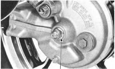
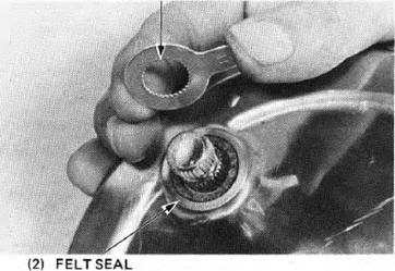
Insta ll the fel t seal and wear ind icator.
I nstall the brake arm, ali gning the punch marks and tighten the brake arm bolt.
TORQUE: 24-30 N·m (2.4-3.0 kg-m, 17-22 ft-lb) (1) WEAR INDICATOR
(1) PUNCH MARKS
SHOCK ABSORB ER REMOVAL
NOTE
Remove one shock absorber at a time to faci litate removal and installa tion.
Adjust the shock absorber to the softest position.
Remove the shock absorber upper and lower moums and remove the shock absorber.
DISASSEMBLY H O ND A
Replace base and guide of shock compressor, P/N 07959-3290001 with base 07959-MBl0000.
NOTE (1) SHOCK COMPRESSO 07959-3290001 (2) COLLAR (3) CLEVIS PIN
Set the shock in the compressor as shown and com press the spring 30 mm l1 1/4 in) by turning the compressor handle.
CAUTION
Place the upper join t in a 11lse and pull the shock rod out.
Separate the upper join t rotating the lock nut in the
(4) BASE ADJUSTER NUT (5) BASE 07969-MBt OOOO
(1)
REAR WHEEL/SUSPENSION BRAKE VTSOOC
Measure the rear shock absorber spring free length.
SERVICE LIMIT:237 mm ( 9.3 in )
ASSEMBLY
Place the spring adjuster. tlhe spring lower seat, spring upper seat and stopper rubber on the damper.
(21 SP ING UPPER SEAT
DP, 131 SPR ING )..-
CAUTION 11) UPPER JOINT
Attach the shock absorber compressor, screwing in the compressor's base adjuster nut.
Apply a locking agent to the damper rod threads and screw the upper joint on. Hold the upper joint in a vise and tighten the lock nut securely,
Check that the lock nut is seated against the rod's bottom thread.
Align the spring seat with the upper jo int while releasing the compressor.
INSTA LLATION
Install the shock absorber onto the frame. Tighten the upper and lower mounts.
TORQUE: 30-40 N·m (3.0-4.0 kg·m,22-29 ft·lbl
(1)
(2)
SWING A RM R EMOVAL
Remove the rear wheel (page 16-3) and the final drive gear case (page 14-3).
Remove the rear shock absorbers (page 16-10).
Remove the swing arm pivot caps and loosen the right pivot bolt lock nut with the lock nut wrench.
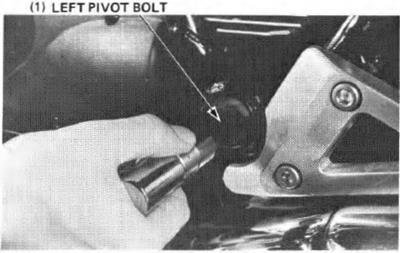
Remove the left pivot bolt and remove the swing arm.
Remove the boot from the swing arm.
( 1) FINAL GEAR CASE
(1)
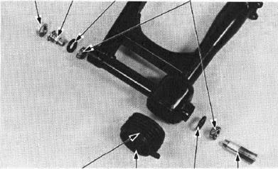
Punch or drill a 13 mm (1/2 in ) hole into each grease retai ner.
Remove the attachment from the special tool, 07936-3710500. Slide the shaft th rough the hole and install a 29 mm (O.D.) washer or equivalent any attachment onto the shaft.
Install the slide hammer and handle remove the race. Repeat for the other side.
NOTE
Install new grease retainer plates and drive new bearing outer races into the swing arm pivot.
(1) DR IVER 07749-0010000
(2) ATTACHMENT, 32 x 35 mm 07746-0010100
INSTALLATION
Apply grease to the pi vot bearing dust seals and pivot bolt tips.
Install the bearings and dust seals.
Install the swing arm boot with its "UP" mark up.
(2) RIGHT (1) PI VOT (3) (4) LOCK N UT BOLT DUST SEAL BEAR INGS
(5) "UP MAR K" (6)BOOT (7)DUST SEAL (8)LEFT PIVOT BOLT
I nstall the swing arm and pivot bolts.
Tighten the left pivot bolt to the specified torque.
TORQUE:80-120 N·m (8.0-12.0 kg-m, 58-87 ft-lbl
Tigh ten the right pivot bolt to 40 N·m (4.0 kg·m, 21 lt·lb) loosen it and retighten to the specif ied torque.
TOR QUE:8-12 N·m (0.8-1.2 kg m, 6-9 ft-lb)
Move the swing arm up and down several times.
R etighten the right pivot bolt to the specified torque.
Tighten the lock nut while holding the right pivot bolt .
TORQUE :80-120 N·m (8.0-12.0 k1t-m .58-87 ft·lb)
Install the final gear case ( page 14-16) and rear wheel (page 16·71.
I nstall the shock absorbers (page 16·12).
HYDRAULIC BRAKES r:;;;J;\ H O ND A
5-35 N ·m (2.5-3.5 kg·m, 18-25 ft-lb)
@
10-14 N ·m (1.0-1.4 kg·m, 7-10 ft-lb)
(2.5-3.0 kg-m, 18-22 ft lb)
30-40 N ·m (3.0-4.0 kg·m, 22-29 ft lb) 20-25 N·m (2.0-2.5 kg·m,,,. 14-18 ft-lbf
|
|||||||||||||||||||||||||||||||||||||||||||||||||
Последнее изменение этой страницы: 2019-06-10; Просмотров: 237; Нарушение авторского права страницы


 I nstall the gear case and drive shaft into the swing

 Install the rear wheel Cpage 16-7). Tighten the axle nut.
 (2.0-2.4 kg-m, 14-18 ft·l b) Install the left shock absorber ( page 16·12).

 H EADLIG HT
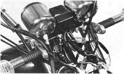
 WIRING CONNECTIONS IN HEADLIGHT CASE


 (1) FORK COVER
 R emove the speedometer and tachometer cables from the instruments.
 Remove the instrument bracket mounting screw and bracket .
 (1) LOWER COVER

 BULB
BULB
 (1) SCREWS
 (1) BULB SOCKETS

 HANDLEBAR SWITCH REPLACEMENT
 Disconnect the brake light switch wires and remove the two screws on the switch housing.


 PIN
PIN


 Disconnect the clutch switch wires and remove the two screws on the switch housing.
 INSTALLATION
 I nstall the upper holder and 1igh ten the forward bolts first, then tighten the rear bolts.
 Connect the choke cable to the choke lever and install the clutch master cylinder. Align the end of the holder with the punch mar k on the handlebar.
 VTSOOC


 (1) THROTILE CABLES
 IGNITION SWITCH
 WI R E CLAMP
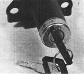
 Assemble the ignition switch in the reverse order of disassembly.
 FUSE HOLDER
 Remove the fuse holder from the hendle bar upper holder.
 FRO N T WHEEL
 Remove the axle pinch bolt.
 DISASSEMBLY
 Remove the side collar and right seal.
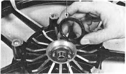

 Stand the wheel up and drive out the bearing from the hub.
 NOTE
NOTE
 BEARIN G R EMOVER EXPANDER
 INSPECTION WHEEL BEARING
 WH EEL
 Check the rim runout by placing the wheel in a truing nend. Spin the wheel slowly and read the runout using a dial indicator.
 AX LE
AX LE


 Do not get grease on the brake disc or stop ping power will be reduced.
 Drive in the right beari ng first and press th e distance colla r into place.
 Drive in the left bearing squarely. NOTE
 Pl LOT, 15mm 07746-0040300
 Install the speedometer gear retainer into the wheel hub, aligning the tangs with the slots.
 Install the right seal and side liar.
 Apply oll to the brake disc bol t threads.

 UTION:


 To balance the wheel, install wheel weights on the highest side of the rim, the side opposite the chalk marks. Add just nough weigh t so the wheel will no longer stop in the same position when it's spun. Do not add more than 60 gra ms.
 INSTALLATION
 Tighten the axle to tne spe<:ified torq ue.
 SPEEDOM ETER GEAR BOX
 BRAKE CALIPER BOLTS
 (21 CAP (3) FORK BRACE
 DISASSEMBLY

 Hold the fork tube i n a vise with soft Jaws or a shop towel and remove the fork tube cap.
 IDo not damage the sli ding surface.
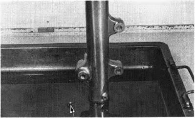


 (11 SNAP RING PLIERS 07914-3230001
 Pull the fork tube out un til resistance from the slider bushi ng Is felt. Then move it in and out, tipping the bushi ng lightly until the fork tube separates from the 1lider. Tne slider bushing will be forced out by the fork tube bushing.
 Remove the oil seal, back-tip ring and slider bushing from the fork tube.
 : ! .:

 Check the fork tube, fork slider and piston for score marks, scr.atches, or exoessive or abnormal wear. Replace any components which are worn or damaged.
 Set the fork tube in V blocks and read the runout. Use 1/2 the total indicator reading to determine the actual runout.
 BUSHING (3) BACK-UP RING

 Before assembly, wash all parts with a high flash point or non -f lammable solvent and wipe them off completely.
 Clean all disassembled parts with non-f lammable or high flash point solvent.
 15-27
15-27


 ,... ;·;c:=4
 NOTE
NOTE

 Install and torque the fork tube cap.
 Install the fork tubes into the :steering stem and fork bridge while rotating them by hand .
 Tigh ten the fork bridge and steering stem pinch bolt on the other side to the specif ic torque.


 EXTENSION BAA 07710020500


 BALL RACE R EPLACEME NT

 (Top ball race installation) (5) ( Bottom ball race installation)
 FRONT WHEEL/SUSPENSION
 A pply grease to the top ball race and insta ll 18 ball bearings.
 (11 PIN SPANNER 07702-0020000
 I n stall the fork bridge and stem nut.

 (3) BRAKE ADJUSTING (41 TORQUE LINK NUT BOLT

 Move the wheel to the right to separate it from the final drive gear case and remove the rear wheel.
 DISASSEMBLY
 WHEEL BEARING REMOVER EXPANDER 07746-0050100
 WHEEL BEARINGS
 Place the wheel in a truing stand and check the wheel bearing play by rotating the wheel by hand. Replace the bearings with new ones if they are noisy or have excessive play.
 WHEEL R IM RUNOUT
 BRAKE DRUM 1.0.

 ASSEMBLY
 DRI VER
 07749-0010000


 AXLE NUT


 BRAKE ADJUSTI NG N UT (4) TORQUE LIN K
 BOLT
BOLT


 REAR WHEEL/SUSPENSION BRAK E
 VT500C
 Place the collar, 62486-463-0000 or equivalent in the shack's bottom joint before pu tting the shock in the compressor.
 UPPER JOINT
 SPRING F REE LENGTH
 (4) SPR ING ADJUSTER
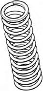
 (5) LOCK N UT--®Q,
 LOWER _........,... SEAT
 Apply a locking agent to the rod threads and install the lock nut.
 NOTE
NOTE
 BASE ADJUSTER NUT (3) CLEVIS PIN
 Remove the right pivot bolt with the 10 mm hex bit.
 SWING ARM PIVOT LOCK NUT WRENCH 07908-ME90000
 PIVOT BEARING REPLACEMENT
 Replace the bearing Inner and outer races as a set. Replace the grease retainer plate whenever it is removed.
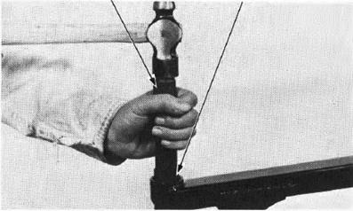


 (11 SWING ARM LOCK N UT WR ENCH 07908-ME90000

 VT500C
 25-30 N·m