
|
Архитектура Аудит Военная наука Иностранные языки Медицина Металлургия Метрология Образование Политология Производство Психология Стандартизация Технологии |
|
|
Архитектура Аудит Военная наука Иностранные языки Медицина Металлургия Метрология Образование Политология Производство Психология Стандартизация Технологии |
OUTPUT GEAR CASE INSTALLATIO N
OUTPUT CASE INSTALLAT ION
I nstall the oil orif ice end dowel pi ns.
GEA R SHIFT OR UM ANO SHIFT FOR K INSPECTION
Inspect the shift drum end for scoring, scratches, or eviden of insufficient lubrication. Check the shift drum grooves for damage.
Measure the shift drum 0.0.
SERVICE LIMIT: 13.90 mm (0.547 in)
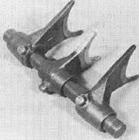
Measure the right, center and eft shift fork 1.0. and the shift fork claw thickness.
SERVICE LIMITS: 1.0.: 13.037 mm (0.5133 in) CLAW THICKNESS: 4.63 mm (0.182in)
(21
( 1) SHIFT FORK
CRANKSHAFT/TRANSMISSION VT500C
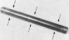
Check for scratches, scoring or evidence of insuffi cient lubrication on the shift fork shaft.
Measure the shift fork shaft O. D. at the right, center and left shift fork surfaces.
SERVICE LIMIT: 12.90 mm (0.508 in)
Install the R.L. forks facing as shown against the center shift fork.
CR A NKCASE BEA RINGS REPLACEM ENT LEFT CRANKCAS E BEA RINGS
Heat the lef t crankcase around the mainshaft and countershaft bearings to 80°C ( 176°F).
CAUTION
Always wear gloves when handling a heated crankcase.
Remove the main and countershaft bearings with the following tools.
Bearing remover, 20 mm 07936-3710001 Drive a new bearing into the left crankcase with the following tools:
Driver A 07749-0010000 Attachment, 42 x 47 mm 07746-0010300
(2)COUNTERSHAFT BEARING
R IGHT CRANKCASE BEARINGS
Heat the ri\tlt crankcase around the mai nshaft, countershaft, output d rive shaf t and shift d rum bearings to 80°C ( 176°F).
CAUTION
Always wear gloves when handling a heated c rankcas e.
Remove the mainshaft and countershaft bearings with the following tools: (2) OUTPUT DRIVE SHAFT BEARING
Bearing remover, 20 mm 07936-3710001
Remove the output drive shaf t arings with the following tools:
(4) COUNTERSHAFT BEARING Driver A Attachment, 42 x 47 mm 07749-0010000 07746-0010300
Drive the new bearings into the right crankcase with the following tools:
Mai n shaft:
Cou ntershaft/output drive shaft:
I nstall the mai nshaft and countershaft assembly on the crankcase.
CR ANKSHAFT/TR ANSMISS I ON H O NDA VT500C
Install the shift forks with their marks facing toward the right crankcase.
Install the shift drum and slide the shift fork shaft throught the shift forks.
Assemble the crankcase (page 12-4) .
(2j SHIFT DRUM
8 mm:23-28 N·m (2.3-2.8 kg·m, 17-20 ft lb) 10 mm: 45-50 N·m
80.-100 N·m (8-10 kg·m, 58-72 ft·lb)
100-120 N·m (10-12 kg·m, 71-87 ft lb)
FINA L DR IVE REMOVA L Place the motorcycle on i ts center stand. Drai n the final gear oil ( page 2·9) and remove the rear wheel (page 16·3).
Remove the left shock absorber (page 16-10).
Remove the final gear case attaching nuts and remove the gear case from the swingarm.
DRIVE SHAFT R EMOVAL
Separate the drive shaft from the gear case by gently revolving the shaft in a circu lar motion while tugging it sl ightly.
(2) Ci!\ H O NDA VT500C
DISASSEMBLY
Remove the spring, oil seal and stop ring from tha drive shaft.
NOTE
Replace the oil seal with a new one if it is removed.
ASSEMBLY
Place a new oil seal over the drive shaft.
I nstal I the damper spring and a new stop ring.
(1) OIL SEA L
t (2) SPRING (3) STOP RING
UNIVER S AL JOI NT A EMOVAUINSTA LLATION
Remove the swingarm (page 16-13).
Remove the un iversal joint from the engine output shaft. \
I nspect the universal joint bearings for excessive play or damage.
Apply grease to the splines and reinstall the univer· sel joint.
FINAL DRIVE GEAR / C ASE RING GEAR REMOVAL
Remove the distance collar.
Remove the dust guard plate bolts. Remove the dust guard plate by turning it clockwise. H ONDA
Place the cover in a press with the ri ng gear down. Make sure the cover is securely supported.
(1) CASE COVER
F INAL DR IVE r::i!J\ HO NDA VT500C
Remove the ring gear from the final drive case. Remove the O·ring guide by tapping it from the opposite side.
R I NG G EAR BEAR IN G REMOV AL
Remove the ring gear bearing and gear adjusting spacer. (1) R ING GEA R
CASE COV E R OI L SEAL R EPLACEME NT
Remove the oil seal from the case cover and press in a new oil seal.
FINAL DRIVE
PINION GEAR REMOVAL
Set the pinion holder onto the pinion joint. Remove the pinion shaft nut. Remove the tool and pinion jo-int.
Remove the retainer bolt lock tab.
H O NDA
(1) PINION HOLDER 07924-ME40000
LOCK NUT WRENCH 07910-MA 10100
FINAL DRIVE Ci/;\ H O NDA VTSOOC
Screw in the pinion puller to the pinion shaft.
Remove the pinion by turning the pinion puller shaft.
PINION BEARING REMOVAL
Remove the O ring from the pinion shaft.
Pull the beari ng off the shaft with the bearing puller.
(t) PINION BEA R ING (1) 0-R ING
(2) BEAR ING PU LLER (COMME RCIALLY AVAI LABLE)
FINAL DR IVE H O NDA VT500C
PINION RETAINER OIL SEAL REPLACEMENT
Remove the 0-ring and oil seal from the pinion reteiner.
Drive a new oilseal into the retainer.
Coat a new 0-ring with oil and install it onto the retainer.
(4)DR IVER 07749-0010000
CASE BEAR I NG AND OI L SEAL REPLACEMENT
NOTE
The ring gear bearing may be removed using bearing remover. 30 mm 07936-8890100.
Remove the ring gear shaft oilseal.
Drive a new oil seal into the case, using the special tools. (3) P NION RETAINER (4) 0RIVER 07749-0010000 (6) ATTACHMENT 07946-3710701 OR 07946-3710700
(2) DRIV ER
FINAL DRIVE H O NDA. VTSOOC
Drive new pinion and ri ng gear b<!arin!JS i nto the case. (1) DR IVER A
(2) DR IVER A 07749--0010000
07746-0040700
BREATHER HOLE CLEANING
Remove the breather hole cap and blow through the breather hole with compressed air.
PINION GEAR ASSEMBLY
Install the original pinion gear $pacer.
NOTE
FINAL DRIVE H ONDA VTSOOC
(1) DRIVER B
Install a new O·ring over the pi n ion shaft.
mo-RING
Place the pinion assembly in'to the gear housing. Drive the pinion assembly into the gear case until the pinion retainer threads can engage with the case threads. Apply gear oil to the 0-ring and threads on the pinion retai ner.Install the 0-ring guide tool.
Screw in the pinion retai ner to press the pinion bearing in place, then tighten it to the specified torque.
TORQUE:100-120 N·m (10-12 kg-m, 72-37 ft-lb)
(1) DRIVER C 07746-0030100 (2)RETAINER
(3) O·RING GUIDE 07973-4630200
RING GEAR ASSEMBLY
Install the original spacer onto the ring gear.
(1)
 RING GEAR SPACER ( RING GEAR BEARING RING GEAR SPACER ( RING GEAR BEARING
lfo . . - •
Place the ring gear bearing over the ring gear shaft.
Install a new O·ri ng onto the 0-ring guide.
Apply grease to the O-ring1 and drive the O·ring guide onto the ring gear shaft:.
COO.RING GUIDE \ll_O-RING
(31 DRIVER A
Measure the clearanc:e between the ring gear and the ring gear stop pin with a feeler gauge.
CLEARANCE: 0.30-0.60 mm (0.012-0.024 inl
turning the cover over and tapping it lightly with a plastic hammer.
CAUTION
Install a stop pin shim to obtain the correct clea r· ance.
SHIM THICK NESS: A: 0.10 mm (0.004 in) B: O.15 mm (0.006 I n)
I nstall the shim and drive the stop pin into the case Cover .
NOTE
Apply liquid sealant to the mating surface of the gear case cover.
Apply a thin coat of Prussian Blue to the pinion gear teeth for a gear tooth contact pattern check. Place the wave washer and ring gear into the gear case. Apply gear oil to the lip of the oil seal on the gear case oover and install the gear case cover. ( 11 PR USSIAN B LUE (2) WAVE WASHER
TORQUE: 23-28 N·m (2.3-2 8 kg-m, 17-20 ft-lb) Then tighten the 10 mm bolts. TORQUE: 40-50 N·m (4.5-5.0 kg m, 33-36 ft-Ibl
Remove the oil filler cap from the final gear case.
Rotate ¢he ring gear several times in the normal direction of rotation. Check the gear tooth contact Pattern th rough the oil filler hole. The pattern is I nd icated by the Prussian Bl ue- applied to the pinion before assembly.
Contact is normal if the Prussian Blue is transferred to the approxi mate center of each tooth and slightly to the flank side.
(21HEE - TOE - (21 - HEEL (3)FACE I - (4)FLANK l6)DRIVE SIDE l13) FACE COAST SIDE l4IFLANK
face. thicker one if the contacts are too high, toward the FINAL DRIVE VT500C
Replace the pin ion spacer with a thin ner one if the contacts are too low, to the flank side. The patterns will shift about 1.5-2.0 mm (0.06-0.08 in) when the thickness of the spacer is changed by 0.10 mm (0.004 in).
PINIONSPACER: A 1.32 mm (0.052 in) B 1.38 mm (0.054 in) C 1.44 mm (0.057 in) D 1.50 mm (0.059 in) E 1.56 mm (0.061 in) F 1.62 mm (0.063In) G 1.68 mm (0.066 in)
BACKLASH INSPECTION
Remove the oil filler cap.
Set the final gear assembly into a jig or stand to hold It stead y. Set a hori zontal type d ial indicator on the ring gear, through the oil filler hole. Hold the pinion gear spline by hand. Rotate the ri ng gear by hand until gear slack is ta ken up. Turn the ri ng gear back and forth to read backlash.
STANDARD: 0.08-0.18 m m (0.003-0.007 in) SERVICE LIMIT:0.30 mm (0.02 in)
Compere the dif ferences of the three measurements.
DIFFERENCE OF MEASUREMENT SERVICE LIMIT:0.10 mm (0.004 in)
(1)
(2/ FLANK (4i FLANK
If backlash is too small, replace the ring gear spacer with a thinner one.
Backlash is changed by about 0.06-0.07 mm (0.002-0.003 in) when thickness of the spacer Is changed by 0.10 mm (0.004 i'n).
RING GEAR SPACER A 1.32 mm (0.052 in) B 1.38 mm (0.054 i n) C 1.44 mm (0.057 i n) D 1.50 mm (0.059 i n) E 1.56 m m (0.061 i n) F 1.62 m m (0 063 in) G 1.68 mm (0.066 i n)
Install the appropriate pinion retai ner lock tab.
NOTE
J There are two types of lock tabs as shown.
I nstall the pi nion joint holder tool and tighten the pinion nut .
TORQUE:80-100 N m (8-10 kg..m.58-72 ft lb) Remove the pinion joint holder tool.
(1) 07924-ME40000
FINAL DRIVE HONDA. VT S O OC Make sure that the gear assembly rotates smoothly with out binding by turn ing the pinion joint.
I nstall the dust guard plate and tigh ten the bol t.
(1)
|
Последнее изменение этой страницы: 2019-06-10; Просмотров: 234; Нарушение авторского права страницы
 (1} DAMPER SPRING (2)DAMPER CAM
 (4} DAMPER COMPRESSOR 07964-ME90000
 Install the output gear case. Tighten the three bolts.
 SHI FT FORK / SHIFT D RUM
 1.0.
1.0.


 (3JSHIFT ORUM BEARING
 TRANSMISSION INSTALLATION


 (4.5-5.0 kg·m, 33-36 ft-lb)
 FIN A L D R I VE
 NUTS
NUTS (2) DRIVE SHAFT

 l
l
 FINAL DRIVE
 VTSOOC
 Remove the eight case cover bolts and cover. If the ring gear stays in the cover, do the following:
 Press the ring gear out of the cover with driver 07749-0010000 and anachment 07746-0010100 while holding the ri ng gear.

 (2)().R ING GUIDE

 (11OI L SEAL

 Remove the pi nion retai n er with the pinion retainer wrench .
 VT500C
 (1IRETAINER
 I nstall the pi nion holder plate onto the final gear case with the final gear case moun tin g nuts.
 )
) R emove the pinion adjustment spacer.

 IOOI L SEAL
 (2) O-R ING(5)ATTACHMENT 07946-3330100
 Heat the gear case to 80°C (176°F). Tap the gear case with a plastic hammer and remove the ring gear and pinion bearings.


 07749-0010000
 (3) ATTACHl')IENT 07945-3330 100
 07749-0010000
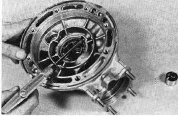


 (1IPINION BEARING (2) PINION SPACER

 Press the bearing onto the pinion gear shaft with the tool as shown.
 LOCK NUT WRENCH 0791G-MA10100
 NOTE
NOTE

 Place a new ring gear bearing bn the ring gear shaft. Place the old bearing on top of it. Then, drive the new bearing onto the shaft with the old bearing and attachment. Then remove the old bearing.
 on49-0010000
 Install the ring gear into the gear case cover.
 Remove the ring gear. If the clearance exceeds the service limit, heat the gear case cover to approxl· mately wJ; °c (176°F). Remove the stop pin by
 Clean all sealing material off the mating surfaces of the gear case and cover.
 GEAR TOOT H CONTACT PATTERN CHECK
 Tighten the cover bolts in 2-3 steps un.ti l the cover evenly touches the gear case, then tighten the 8 mm bolts to the specified torque in a crisscross pattern in two or more stepS.
 IllNORMAL

 If the patterns are not correct, remove and replace the pinion spacer. Replace the pinion spacer with a

 Remove the dial indicator. Tum the ring gear 120° and measu re backlash . Repeat this procedure once more.
 TOO LOW
 (3) DRIVE SIDE COAST SIDE
 If the difference in measurements exceeds the limit. it indicates that the bearing is not installed squarely. Inspect the bearings and reinstall if necessary .
 PINION JOINT INSTAL LATION
 Apply gea r oil to the oil seal lip contact surf ace of the pinion joi nt and install the pi nion join t.
 PINION HOLDER

 DUST GUARD PLATE