|
Архитектура Аудит Военная наука Иностранные языки Медицина Металлургия Метрология Образование Политология Производство Психология Стандартизация Технологии |
|
|
Архитектура Аудит Военная наука Иностранные языки Медицина Металлургия Метрология Образование Политология Производство Психология Стандартизация Технологии |
Aircraft According to Fuselage Size
A wide-body aircraft, also known as a twin-aisle aircraft, is a large airliner with two passenger aisles (проход). The typical fuselage diameter is 5 - 6 m (16 - 20 ft). The largest wide-body aircraft are over 6 m (20 ft) wide. Wide-body aircraft are also used for the transport of commercial freight and cargo and other special uses. In contrast, a narrow-body aircraft is an airliner with a fuselage aircraft cabin diameter typically of 3 - 4 meters (10 - 13 ft), and a single aisle. It is often called single-aisle aircraft. Narrow-body aircraft with a range not allowing transatlantic or transcontinental flights are commonly known as regional airliners. For comparison, typical wide-body aircraft can accommodate between 200 and 600 passengers, while the largest narrow-body aircraft currently in widespread service (the Boeing 757-300) has a maximum load-carrying capacity of about 250 passengers.
The Ilyushin Il-96 (Russian: Ил-96) is a four-engined long-range widebody airliner. It is manufactured by the Voronezh Aircraft Production Association. The Il-96 has three main variants (Il-96-400T is the freighter version). Its first flight was in September, 1988, and the plane was introduced into service in 1992. Since 1988 24 aircraft have been built, 16 of them are operational now. The basic Il-96-300 is equipped with modern Russian avionics integrating six multi-function color LCD displays, inertial and satellite navigation systems, and a Traffic Collision Avoidance System. The airplane features supercritical wings fitted with winglets, a glass cockpit, and a fly-by-wire control system.
Flight performances
Tu-204
The Tu-204 is a twin-engined medium-range airliner carrying 212 passengers. First introduced in 1989, it is considered to be equivalent to the Boeing 757. It is produced at two of the largest Russian aircraft manufacturing plants in Ulyanovsk (Tu-204) and Kazan (Tu-214). Both economy class and business class compartments are provided with passenger seats of improved design with 3+3 and 2+2 seating arrangements, respectively. The Tu-204 belongs to a new generation of Russian aircraft, including other recent developments such as the Ilyushin Il-96. As for variants, the Tu-204 is the basic passenger airline model, and the Tu-204C is the basic freight model. The mostly used models are the -100C and the -120C. Flight performances
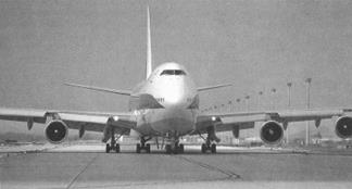
Boeing-747-300
Boeing-747-300 is a four-engined long-range airliner manufactured by the American Boeing. It is a modification of 747SUD with a stretched upper deck which provides accommodation for additional 44 passengers. Changes were also made to the main deck to allow additional passengers to be carried in an all-economy arrangement. The airplane is being used since 1983. The customers for the production -300 included Egyptair, Korean Air, Malaysian, Sabena, Saudia, Singapore, South African and others. The only -300 was lost at Paris Charles de Gaulle airport on March 16, 1985 when it was destroyed by fire while undergoing maintenance. Interestingly, a similar fate awaited an A340 at the same location ten years later. Flight performances
Airbus-340
The ultra-long-range A340 is an all-new, wide-body, four-engine, twin-aisle aircraft. It is offered in two models, the -200 and -300 whose length is increased by two four-frame fuselage plugs. The design combines the high technology, developed for the A320, with the vast experience gained from the A300 and A310 aircraft currently in worldwide service. Since its introduction in early 1993, the aircraft has been the most advanced long-range airliner offering a major stride forward in airline profitability.
Flight performances
Supplementary Reading
Flight Controls
Flight controls have advanced considerably throughout the years. In the earliest biplanes flown by the pioneers flight control was achieved by warping wings and control surfaces by means of wires attached to the flying controls in the cockpit. The figure shows the multiplicity of rigging and control wires on an early monoplane.
When top speeds advanced into the transonic region the need for more complex and more sophisticated methods became obvious. The controls used by a typical commercial airliner are described below.
tion itself is powered by two or more actuators in order to trim the aircraft in pitch. In a dire emergency this facility could be used to control the aircraft, but the rates of movement and associated authority are insufficient for normal control purposes. Roll control is provided by two aileron sections located on the outboard third of the trailing edge of each wing. Each aileron section is powered by a dedicated actuator powered in turn from one of the aircraft hydraulic systems. At low air speeds the roll control provided by the ailerons is augmented by differential use of the wing spoilers mounted on the upper surface of the wing. During a right turn the spoilers on the inside wing of the turn, that is the right wing, will be extended. This reduces the lift of the right wing causing it to drop, hence enhancing the desired roll demand. Yaw control is provided by three independent rudder sections located on the trailing edge of the fin (or vertical stabilizer). These sections are powered in a similar fashion to the elevator and ailerons. On a civil airliner these controls are associated with the aircraft yaw dampers. These damp out unpleasant ‘dutch roll’ oscillations which can occur during flight and which can be extremely uncomfortable for the passengers, particularly those seated at the rear of the aircraft. Fuel system components Fuel transfer pumps perform the task of transferring fuel from wing tanks to the fuselage centre tank where fuel may typically be consolidated before engine feed. Fuel booster pumps, sometimes called engine feed pumps, are used to boost the fuel flow from the aircraft fuel system to the engine. One of the reasons for this is to prevent aeration (i.e. air in the fuel lines that could cause an engine ‘flame-out’ with consequent loss of power). A variety of fuel valves will typically be utilized in an aircraft fuel system. Shut-off valves perform the obvious function of shutting off fuel flow when required. This might involve stemming the flow of fuel to an engine, or it may involve the prevention of fuel transfer from one tank to another. Refuel/defuel valves are used during aircraft fuel replenishment to allow flow from the refueling gallery to the fuel tanks. These valves will be controlled so that they shut off once the desired fuel load has been taken on board. Similarly, during defueling the valves will be used so that the load may be reduced to the desired level. Cross-feed valves are used when the fuel is required to be fed from one side of the aircraft to the other. Fuel dump valves perform the critical function of dumping excess fuel from the aircraft tanks in an emergency. These valves are critical in operation in the sense that they are required to operate and dump fuel to reduce the fuel contents to the required levels during an in-flight emergency. A variety of non-return valves or check valves are required in an aircraft fuel system to preserve the fluid logic of the system. Non-return valves as the name suggests prevent the flow of fuel in the reverse sense. The use of non-return valves together with the various transfer and shut-off valves utilized around the system ensure correct system operation in the system modes. Level sensors measure the fuel level in a particular tank and thereby influence fuel management system decisions. Level sensors are used to prevent fuel tank overfill during refuelling. Level sensors are also used for the critical low-level sensing and display function to ensure that fuel levels do not drop below flight critical levels where the aircraft has insufficient fuel to return to a suitable airfield. Level sensors may be one of a number of types: float-operated; optical; ultrasonic. Quantity measurement is usually accomplished by a number of probes based upon the principle of fuel capacitance measurement at various locations throughout the tanks. Air and fuel have different dielectric values and by measuring the capacitance of a probe the fuel level may be inferred. These locations of the fuel probes are carefully chosen such that the effects of aircraft pitch and roll attitude changes are minimized as far as quantity measurement is concerned. Additional probes may cater for differences in fuel density and permittivity when uplifting fuel at differing airfields around the world as well as for fuel at different temperatures. Fuel gauging, or fuel quantity indication systems (FQIS) as they are sometimes known, are therefore an essential element in providing the flight and ground crews with adequate information relating to the amount of fuel contained within the aircraft tanks.
Aircraft Hydraulics Hydraulic systems made their appearance on aircraft in the early 1930s when the retractable undercarriage was introduced. Since that time an increasing number of tasks have been performed by the application of hydraulic power and the power demand has consequently increased greatly. The hydraulic system today remains a most effective source of power for both primary and secondary flying controls, and for undercarriage, braking and anti-skid systems. However more-electric systems are being considered to replace hydraulically powered systems in some areas. In its simplest form a hydraulic system is as follows. The primary source of power on an aircraft is the engine, and the hydraulic pump is connected to the engine gearbox. The pump causes a flow of fluid at a certain pressure, through stainless steel pipes to various actuating devices. A reservoir ensures that sufficient fluid is available under all conditions of demand. To achieve the levels of safety requires at least two hydraulic circuits as shown in the figure. The degree of redundancy necessary is very largely controlled by specifications and mandatory regulations issued by the national and international bodies charged with air safety. The requirements differ considerably between military and civil aircraft. Military aircraft frequently have two independent circuits, large civil transports and passenger aircraft invariably have three or more.
Under normal working conditions hydraulic fluid needs cooling and cleaning. Occasionally it is necessary to de-aerate by the connection of ground equipment, although increasingly modern systems are being produced with devices to bleed off any air accumulating in the reservoir. For cooling purposes the fuel/hydraulic heat exchanger is used. This ensures that cooling on the ground is available. Further air/fluid cooling may be provided once the aircraft is in flight. Since heat exchangers are low-pressure devices they are normally situated in the return line to the actuator/service. When a pump is running off-load, all the heat generated by its inefficiencies is carried away by the pump case drain line. The heat exchanger should therefore be positioned to cool this flow before its entry into the reservoir. Care must be taken to determine the maximum pressure experienced by the heat exchanger.
Electricity for Aircraft All modern aircraft and spacecraft depend on electricity and electronics. Electronics is a special application of electricity. Avionics is the term for electronics when it is applied to aircraft. We know electricity performs many functions in the airplane. Electricity supplies light, heat and power. It ignites fuel-air mixture in the engine. It operates light, retractable landing gear, wing flaps, engine cowl flaps, radio and navigation equipment. We use electricity for ground control, operation of different mechanisms, computers, communication, etc. Nowadays the pilot has airborne avionic system with improved reliability and performance. Reliability is increased by a combination of improved components and better system design. Performance is improved primarily by the large-scale use of on-board digital computers. On-board equipment processes data from various sources and performs computations for navigation and flight control. Reliable air-to-ground communication in remote areas is provided by a satellite system. An aircraft complexity increases, the number and complexity of instruments and equipment with electronic control also increases. A great number of various display devices is and will be widely used for multiple applications. Aircraft Instruments Avionics is aterm used for electrical, electronic, radio and other aircraft instruments, which assist the crew in controlling the machine and monitoring the operation of various aircraft systems According to their function aircraft instruments are traditionally divided into flight and navigation instruments and engine control instruments. The former provide data for the flight control and navigation, while the latter secure reliable operation of the power plant. Instruments are needed to measure pressure, temperature, altitude, velocity, rate of flow and numerous other conditions and parameters affecting the flight and operation of aircraft. The pilot must be provided with accurate information on all these factors. Most of these instruments contain special types of sensors receiving input data, circuits for their transmission, and indicators for the information display. The information obtained from various sensors can also be used for the purpose of automatic flight control In this case output signals are transmitted to the servomechanisms, which actuate the necessary controls. Flight instruments can be grouped according to the type of sensors There is a large class of instruments based on aneroid sensors. The instrument that indicates the altitude of the aircraft above the ground is called an altimeter. Another very important device is an airspeed indicator. The vertical speed indicator serves to measure the rate of the aircraft climb and descent. Electricity and Avionics All modern aircraft and spacecraft are very dependent upon electricity arid electronics. Avionics is the term for electronics as applied to aircraft. One of the prime functions of the electrical equipment in an airplane is to ignite the fuel -air mixture in the engine. In addition the electrical system provides light, heat and power. Besides it operates different lights, retractable landing gear, wing flaps radio, instruments and navigational equipment. Electricity and electronics are needed for ground control computer, communication, etc. in short we employ electricity to perform multitude of tasks. Modern planes contain many miles of electrical wiring and hundreds of electrical and electronic components. Without electricity arid electronics there would be no modern airplanes, missiles or spacecraft. Today modem aircraft vehicles are equipped with scores of different electrical systems. To supply the power for these systems, the vehicles arc equipped with generating equipment sufficient to provide light for a town. It is obvious that one of the most important factors in reliability of any aircraft is reliability of its electrical system. It is electrical system that is needed for the control of propulsion system, for control of guidance and navigation, for communication. The operation of modern aircraft could not exist without the use of instruments. All instruments are usually operated electrically or electronically. There is no quicker, easier or more reliable method of conveying information from every section of airplane to the flight crew than by means of electric circuits and devices.
Cockpit and its Equipment The cockpit is where the crew members sit. It is a portion of the fuselage front where the aircraft is taken to the air, controlled in flight and landed. The cabin is equipped with a great variety of instruments, devices and equipment. The efficient utility of modern aircraft depends largely on the ability of instruments to depict accurately what the aircraft is doing in flight and how well its power plant and components are functioning. In addition to instruments a variety of radio equipment is required to provide efficient navigation. The combination of aircraft instruments, radio equipment and the use of electronics in its instrument design is called avionics. Basic flight instruments are the instruments which a pilot uses to fly an aircraft. To understand their role better they are divide into three categories: control instruments, performance instruments and navigation instruments. Control instruments. Primary control instruments are of great importance. They are tachometer, temperature indicator, fuel quantity indicator, cabin pressure indicator, the undercarriage position flag. Performance instruments. Primary performance instruments on the instrument panel of the front and rear cabins are: the combined airspeed indicator, the Mach meter, vertical velocity indicator, altimeter (radio altimeter), attitude indicator, the clock and many other instruments. Navigation instruments. Primary navigation instruments are the radio compass and distance measuring equipment: distance ground speed indicator, distance indicator and some other instruments.
Air Navigation Air navigation came into existence alongside with air traffic. It had a humble beginning, but in a little more than 50 years has come today's extensive aircraft industry, a vast network of global airlines. In the early days of flying, serious accidents often occurred because men were not thoroughly familiar with the new medium of transportation. Today pilots are familiar with the construction of the aircraft, its controls, and its limitations. Competent instructors are available to give this information as well as to give actual flight instructions. The manuals are based not only on sound theory but also on long experience. They should be obtained and carefully studied. The directing of aircraft from one place to another is the science of air navigation. In fair weather and during daylight, it is usually not difficult to fly from one place to another by visual reference to landmarks noted in the charts. In bad weather and in the hours of darkness, the usual landmarks are often lost to view. Even the airport of the destination may be closed. If air transportation is to function safely and with any degree of regularity, some aids to navigation, including instrument landing facilities, must be made available. With the installation of instrument landing systems at principle terminals, and with other equipment such as radar and radar beacons, we may confidently expect that air transportation soon will become independent of all but the most severe weather conditions.
Navigator’s Role
Ever since thetime when people found their wayby using a column of smoke by day and fire by night, navigation, navigational techniques, and navigational aids have been the subject of discussion. What is navigation? - Navigation is the art of determining the geographical position and maintaining desired direction of an aircraft relative to the earth's surface. A navigator belongs to the flying staff of the crew. He performs his duties by means of navigational aids and different instruments installed along the airways as well as in a plane and by making numerous calculations. That's why a navigator must know technical aids of air navigation and methods of their application during flight perfectly well. He should make navigational preparations for flight in good time. The navigator's duties performed by him during flight, are rather numerous: he must navigate the plane according to the flight plan from take off to touch down; control the progress of the aircraft by means of all established navigational methods and technical aids. He must know and observe the rules of radio communication and keep watch on airborne aids. The navigator has to get flight charts prepared personally and in advance. In addition to all duties mentioned above he must make a correct estimate of the meteorological situation. In the course of preliminary preparation of the crew for flight the navigator together with other members of the flying staff studies the order of conducting flight on a given airway and radio aids available. Navigator's task is to determine aircraft's position, direction and speed of flight. Usually navigators fly on heavy planes. As aircraft become larger and faster, requirements to navigator's work increase. Longer flights sends out radio waves and then measures the amount of time that it takes for the waves to return. A radar set includes a transmitter and a receiver. The transmitter sends out at regular intervals short pulses of high-frequency waves. These can penetrate clouds and darkness. They move out in a straight line. Having met some object they are reflected back to the radar set and are translated into a spot of light on the screen. Ground radar is used to guide planes to a landing in bad weather.
Airbus A-308 The 555 seat, double deck Airbus A380 is the most ambitious civil aircraft program yet. When it enters service in March 2006, the A380 will be the world's largest airliner. Airbus first began studies on a very large 500 seat airliner in the early 1990s. The European manufacturer saw developing a competitor and successor to the Boeing 747 as a strategic play to end Boeing's dominance of the very large airliner market and complete Airbus' product line-up. Airbus began engineering development work on such an aircraft, then designated the A3XX, in.June 1994. Airbus studied numerous design configurations for the A3XX and gave serious consideration to a single deck aircraft which would have seated 12 abreast and twin vertical tails. However, Airbus settled upon a twin deck configuration, largely because of the significantly lighter structure required. Key design aims include the ability to use existing airport infrastructure with little modifications to the airports, and direct operating costs per seat 15-20% less than those for the 747-400. With 49% more floor space and only 35% more seating than the previous largest aircraft, Airbus is ensuring wider seats and aisles for more passenger comfort. Using the most advanced technologies, the A380 is also designed to have 10-15% more range, lower fuel burn and emissions, and less noise. The A380 would feature an advanced version of the Airbus common two crew cockpit, with pull-out keyboards, for the pilots, extensive use of composite materials such as GLARE, and four turbofan engines now under development. Several A380 models are planned: the basic aircraft is the 555 seat A380-800 and high gross weight A380-800, with the longer range A380-800R planned. The A380-800F freighter will be able to carry a 150 tonne payload5 and is due to enter service in 2008. Future models will include the shortened, 480 seat A380-700, and the stretched, 656 seat, A380-900. (The -700, -800, and -900 designations were chosen to reflect that the A380 will enter service as a " fully developed aircraft" and that the basic models will not be soon replaced by more improved variants). With orders and options from nine world-renowned customers (Air France, Emirates (the first customer), Federal Express, International Lease Finance Corporation, Lufthansa, Qantas, Qatar Airways, Singapore Airlines, and Virgin Atlantic), the Airbus A380 was officially launched on December 19, 2000, and production started on January 23, 2002. More airlines have placed orders since. The out of sequence A380 designation was chosen as the " 8" represents the twin decks. The entry into commercial service, with Singapore Airlines, is scheduled for March 2006. A380 final assembly will take place in Toulouse, France, with interior fitment in Hamburg, Germany. Major A380 assemblies will be transported to Toulouse by ship, barge and road. Популярное:
|
Последнее изменение этой страницы: 2017-03-08; Просмотров: 1209; Нарушение авторского права страницы