
|
Архитектура Аудит Военная наука Иностранные языки Медицина Металлургия Метрология Образование Политология Производство Психология Стандартизация Технологии |
|
|
Архитектура Аудит Военная наука Иностранные языки Медицина Металлургия Метрология Образование Политология Производство Психология Стандартизация Технологии |
Remove t ht 1t1 rte r motor case rews .⇐ ПредыдущаяСтр 19 из 19
Inspect the brushes and measure the brush length. Measure brush spring tension with a spring scale. SERVICE LIMITS: Brush length: 6.5 mm (0.26 in> Brush spring tension: 545 g (19.2 oz>
COMMUTATOR INSPECTION
Remove the starter motor case.
(2) BRUSH LENGTH (1IBRUSH SPRING
IllCOMMUTATOR
NOTE
Check for contin uiw between pai rs of commutator bars. Also, make a resistance check between in· d lvidual commu tator bars and the armature shaft. There should be no continuity.
(1ICONTINUITY BETWEEN COMMUTATOR BAR PAIRS: NORMAL
(2) NO CONTINUITY BETWEEN COMMUTATOR BARS AND ARMATURE SHAFT:NORMAL
ASSEMB LY/INSTALLATION
Assemble the starter motor. Align the case notch with the brush holder pin.
Install the rear cover aligning its slot with the brush holder pin.
Install the starter motor in the reverse order of removal
Connect the water pipe. Refill the radiator with coolant (page 6-4). Install the right rear muffler.
STARTER RELAY SWITCH INSPECTION
Depress the starter switch button with the ignition ON. The coilis normal if the starter relay switch clicks.
Connect an ohmmeter to tlhe starter relay switch terminals.
Connect a 12 V battery to the switch cable termi nals.
The switch is normal if thereis continuity. (1) BRUSH HOLDER (2)NOTCH (3) PIN (4) CASE
(11 PIN (2) BRUSH HOLDER (3) SLOT
ELECTR IC STARTER VT500C
REMOVA L
Remove the fuel tank.
Remove the clutch diode from the wire harness.
INSPECTION
Check for continuiw with an ohmmeter . (1) IN ONE DIRECTION: CONTINUITY (2)
SWITCHES
OIL PRESSURE SWITCH Drain the engine oi l.
Disconnect the oil pressure switch lead and remove the switch.
Check for continuity while applyi ng pressure to the switch.
Replace the switch ii neces.sa ry.
Apply a liquid sealant to the switch threads before installing the switch . Screw the switch i n the crankcase and leave two th reads from the bottom. Then tighten it to the sPecified torque. TORQUE :10-14 N·m (1.0-1.4 kg-m, 7-10 ft·lb) fA\ H O NDA
111 CONTINUITY : BELOW 2.8 psi
NO CONTINUITY :ABOVE 2.8-5.6 psi
Be sure the rear brake light switch is properly adjusted (page 3-15).
Then check the rear bra ke light switch for con tinuity with the rear brake applied.
Check the front brake light switch for continuity with the front brake applied .
Replace either switch i f there is no contin uity when the correspondi ng brake is applied.
NEUTRAL / DD SWITCHES
Check the continuity of the switches with the
Shift the transmission into neutral. Remove the left crankcase rear cover and gear shift linkage.
Remove the mounting bolts and switch.
INSTALLATI ON
Position the switch rotor pin as shown and install the switch by aligning the pin with the groove of the gear shift drum.
Disconnect the wire leads from the clutch switch.
Check the continuity of the cl utch lever (saf ety) switch with the clutch released and applied. Replace if necessa ry.
LEVER APPLIED: CONTllllUITY LEVER NOT APPLIED: NO CONTINUITY HANDLEBAR SWITCHES The handlebar cluster switches (ligh ts , turn signals. horn, etc.) must be replaced as assemblies. •
Remove the headlight and headligh t case.
Continuity tests for the components of the handle· bar cluster switches follow:
Continuity should exist between the color coded wires in each chart.
HEADLIGHT HI-LOW SW ITC H (!) HEADLIGHT HI-LO SWITCH
(21HOR N BUTTON (31TURN SIGNAL SWITCH
Headlight Hi-Low Switch
HI: MIDDL E (N): LO: B/W to B
TURN SIGNAL SWITCH
LEFT: Gr to 0 Turn Signal Switch
R IGHT: Gr to LB
HOR N BUTTON
LG to W I G with button depressed ; continuity. No continuity with button released.
0 (-") v-
Bk to Y/R with button pushed in; continuity. Bk to Y/R with button out; no continuity.
Starter Button
ENGINE STOP SWITCH RUN: Bk to Bk/W; continuity. OFF: No continuity.
LIGHTING SWITCH OF F: No continuity P : Br/B to BrN/; continuity HL : Br/B to BrNI. BNI to Bk/R; continuity
IGNITI ON SWITCH Remove the headlight, headlight case and instru ment lower cover and disconnect the ignition switch coupler.
Check continuitV of terminals on the ign ition switch coupler in each switch position.
SWITCH POSIT ION .-...
LOCK : OFF: ON: PAR K: No, continuity. No continuity.
n-
(-)
SWITCHES VTSOOC THERMO S TATIC SWIT C H The cooling fan motor is actuated by the thermo static switch loMt•rl in the left tank of the radia tor.
Run the engine until coolarlt temperature reaches 80-102°C (176-216°F) . The fan motor should start running. The fan motor should stop when the coolant temperature drops to 93-97°C (200- 2070F).
Turn the igni tion switch on. The cooli ng fan motor should start running. If it s-tarts, replace the fan thermostatic switch and retest. ·
If it does not start, check for battery voltage from the B lead (positive) to the B/L lead (negative) of the fan motor coupler. If there is no voltage, check for a blown or faulty fuse, loose terminals or connectors, or an open circuit.
TEMPERATURE SENSOR Remove the f uel tank . Disconnect the G/B wire from the temperature sensor.
(l) WIRE
Check the temperature of the coolant.
Run the engine and measure the change i n resistance of the sensor with the coolant at the temperatures shown in the chart,
Replace the sensor if it i·s out of specifications by more than 10% at any temperature listed.
Remove the fuel ta nk. Disconnect the wi re from the temperatu re sensor and short it to ground.
Turn the ignition switch to ON. The temperatu re gauge needle should move a II the way to the right.
(1) TEMPERATU RE GAUGE
(2)
|
|||||||||||||||||||||||||||||||||||||||||||||||||||||||||||||||||||||||||||||||||||||||||||||||||||||||||||||||||||||||||||||||||||||||||||||||||||||||||||||||||
Последнее изменение этой страницы: 2019-06-10; Просмотров: 200; Нарушение авторского права страницы


 Inspect the commutator bars for discoloration. Bars discolored in pairs indicate grounded armature coils.


 (4) REAR BRACKET


 CLUT C H DIODE
 IN THE REVERSE DIRECTJ9N:NO CONTINUITY
 VT500C

 CAUTIOM
 BRAKE LIGHT SWITCH
 Remove the seat and fuel tank and disconnect the neu tralfOD switch connector.
 transmission i n each gear position .
 R EMOVA L
 CLUTCH SWITCH
 B/W to W to B B/W to W
 R L
R L Horn Button
 STARTER BUTTON
 R to Bk, BrNI to Br;continuity. Br to R;continuity.
 If the fan motor does not start, discon nect the B/L and G leads from the thermostatic switch and short them together with a jumper wire as shown.
 THERMOSTATIC SWITCH LEADS (2) JUMPER

 With the engine cold, use an ohmmeter to measure resistance between the tem perature sensor terminal and the engine.
 TEMPER A T URE GAUG E
 CAU TIO N
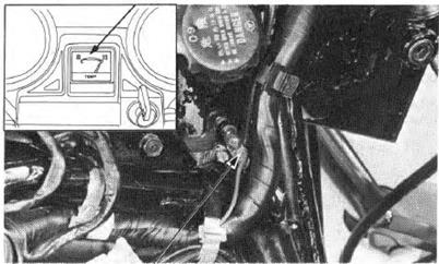
 TEMPERATU R E SENSOR
 SWITCHES